Page 1 of 1
RSSI info / provide signal strength
Posted: 05 Jan 2017, 19:51
by data
While on my search for the best receiver module for RFLink, I stumbled over the RXB6
Version 2!
Besides being a sensitive receiver anyway, its main advantage over any other receiver seems to be, that
it has an additional analog RSSI-signal output. Connecting this pin to an analog input of the Mega2560 will
enable you to get the signal strength of the received device!
See datasheet (PDF) at
http://www.rficy.com/wp-content/uploads ... 2/CY07.pdf
I just ordered one, since it's really cheap - €1.21, free shipping:
http://s.click.aliexpress.com/e/7Q3J2Nj
Anybody else thinks that this is a great feature?
Re: RSSI info / provide signal strength
Posted: 05 Jan 2017, 20:28
by Stuntteam
Sounds good..
Re: RSSI info / provide signal strength
Posted: 06 Jan 2017, 09:40
by Justblair
I have tried to find the RSSI. The datasheet does not really make it clear as to how you enable the "optional" RSSI
I tried opening the metal case up and connecting to one of the pins (I believe it is an analog signal). But I grew frustrated when I could not get any really sensible readings from it.
Tell us how you get on. I wanted to use this to create a very cheap rf location device for model rockets.
Re: RSSI info / provide signal strength
Posted: 06 Jan 2017, 11:04
by Stuntteam
RSSI (analog) signal should be on pin 6 (DER)
I guess the problem is how to trigger mode 3..
In normal operation pin 6 is a copy of pin 7
Then you can pull pin 6 high or low to affect the operation mode.
But how to get it in mode 3.. ?!
Re: RSSI info / provide signal strength
Posted: 06 Jan 2017, 11:28
by data
From what I understand, only v2.0 of this module provides RSSI out.
Maybe versions < 2.0 has some parts missing or a different pcb.
See e.g.
http://www.jmrth.com/en/rxb6.asp
> ...
> Analog RSSI Output (only for V2.0)
Which version do you have? Can you post a photo? What is printed on the back of the pcb?
Re: RSSI info / provide signal strength
Posted: 06 Jan 2017, 11:42
by data
@justblair: Here's one for you:
http://www.instructables.com/id/433-MHz ... /?ALLSTEPS
I just found something else: Apparently, the SYN470RF IC also offers RSSI on pin 13 (CAGC):
... voltages presented here [on PIN 13] ranged from ~1.34V (when beside a companion 433 MHz beacon transmitter) to ~2.54V no signal. ...
http://www.picaxeforum.co.uk/showthread ... -RSSI-hack
Update: Here's the SYN470 Datasheet:
http://ex.kabobo.ru/tw_files2/urls_26/4 ... docs/2.pdf
Please add a small subroutine which measures the voltage on an analog input and (perhaps optionally - 10;RSSI=on; ) appends that value to the serial output.
Re: RSSI info / provide signal strength
Posted: 06 Jan 2017, 11:44
by Stuntteam
v2.0 would be the industrial version. The problem is not so much the version though..
But rather how you get the module into this 3rd operation mode so that the RSSI signal is supplied on the DER pin (pin 6).
I have not found any datasheet or info that shows what to do.
In default mode it just supplies data and is the same as pin 7. This to be pinout compatible with other modules.
Alternatively, we could check the SYN470R (315mhz)/SYN480R (433mhz)
It does only have pins for vcc/ground/data but on the chip itself, pin 7 is CACG which would be an RSSI signal..
This could be hooked to one of the analog pins of the Mega and we can have the rflink code read the value and forward the rssi.
Most of the SYN modules have the small 8 pin chip.. in that case pin 7 is CACG
Re: RSSI info / provide signal strength
Posted: 06 Jan 2017, 15:14
by data
Here's something that might save you some time when implementing the RSSI output.
Despite being developed for the analog RSSI output of a RFM12B, it should be somewhat
similar to our modules:
https://hallard.me/rfm12b_arssi-library/
Re: RSSI info / provide signal strength
Posted: 06 Jan 2017, 20:45
by data
@Stuntteam:
And when you are at it, please also add some kind of heartbeat for the noisefloor:
a periodic (e.g. maybe 1 or 5 minutes interval?) reporting of the background noise.
That would be really great!
Re: RSSI info / provide signal strength
Posted: 07 Jan 2017, 00:51
by Stuntteam
uh.. not sure what you mean with that..
We already have a ping/pong mechanism that is used by Domoticz etc to check if RFLink is still functional..
Re: RSSI info / provide signal strength
Posted: 07 Jan 2017, 01:15
by data
Ok, heartbeat is the wrong word.
Basically, I'd like to monitor the noisefloor on 433MHz - similar to a temperature sensor sending regular data.
So I thought of not just providing the RSSI when a signal is received but also give me an average of the idle
or background noise value every n minutes. Know what I mean?!
Re: RSSI info / provide signal strength
Posted: 14 Jan 2017, 12:29
by data
Update: RSSI Out works!
I just received one of the RXB6 modules I ordered and it is V2.0.
This version provides RSSI Out without any modifications on the DER pin.
Get yours for just US$1.21 on AliExpress:
http://s.click.aliexpress.com/e/IybEuny
With 20cm wire attached to the antenna pin I measured an idle voltage of
approx. 2.7V for background noise and a noticeable drop to below 2V when
receiving a signal.
So the only hardware modification needed for RFLlink is to add a wire between
the DER pin and one of the analog-in ports of the mega 2560.
@stuntteam:
Please give us RSSI readings in the next release!
Re: RSSI info / provide signal strength
Posted: 26 Jan 2017, 20:08
by data
Meanwhile, I received the second RXB6 I ordered.
This one looks different from the first one. Besides a golden Q.C. Passed Sticker (the other one is silver) it has almost no markings.
The first one I received has "RXB6" printed on the back and below it reads "V2.0". Then, there is a timestamp field with 2014, 2015 and numbers 1 to 12.
Also, when measuring voltage on the supposed RSSI pin, the new one gives only values between 1 and 2 volts. (I have no Osci atm)
Connecting the GPIO to the supposed RSSI pin confirmed my expectation: There is no RSSI but the same data-out signal as on the
original data-out pin. So, this one is either a clone or at least not version 2.0 as claimed by the seller.
Is there already a beta Version available with RSSI support? If so, I'd love to try it out with the working one!
Re: RSSI info / provide signal strength
Posted: 10 Feb 2017, 08:13
by RCcocktail
I to purchased some RXB6 receivers V2.0. They seemed legit, but I could not get RSSI to work. The DER pin was a duplicate of the DATA pin, so I though I was mislead. Then I found the following link on ebay:
http://www.ebay.com/itm/433-92MHz-433MH ... 1631674225
In the description it indicates:
For Pin 6 , it is R/E/D optional , R mean RSSI , E means Enable , D mean Data ( defult).
RSSI mode : please Romove R6 resistance to R7;
Enable modes: please Romove R6 resistance to R5 .
So I guess you just wire across the resistor??

Hope this helps!
Re: RSSI info / provide signal strength
Posted: 10 Feb 2017, 19:04
by RCcocktail
I did some more research. The RXB6 that I have use the SYN500R chip. See the datasheet for the SYN500R chip at
http://www.xie-gang.com/SYN500R.pdf
I looked at the RXB6 board and the chip's RSSI pin is not connected to anything (see attached pic).
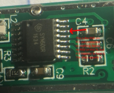
- SYN500R chip. Pin 3 is RSSI. On this board it's not connected.
- pin3.jpg (103.69 KiB) Viewed 25722 times
Re: RSSI info / provide signal strength
Posted: 10 Feb 2017, 19:31
by data
I've compared both modules V2.0 and the older one without RSSI and there is no difference.
Both have the R6 with 0Ohm and the others not populated. Version 2.0 apparently provides
RSSI, the other one does not.
Can you make a photo of the back side of your module and upload it here?
Re: RSSI info / provide signal strength
Posted: 13 Feb 2017, 15:16
by RCcocktail
I think I figured it out - at least it works for me. I have the same board as you have (white sticker in your picture). On mine the RSSI was not enabled. I enabled it by soldering the two contact point together in the red circle.
Out of interest, I destroyed one board by taking off the chip to inspect. What I found is that pin 3 (RSSI) on the chip as indicated in my previous post is connected to a pathway on the back of the board leading to the DATA pin. If you solder across as I did, apparently you remove the resistance and RSSI functions properly - at least for me.
Let me know if you try soldering the gold sticker board and it works.

- Back side of RXB6 module with white sticker
- IMG_0297.JPG (232.57 KiB) Viewed 25690 times

- RXB6 soldered to enable RSSI
- IMG_0298.JPG (226.13 KiB) Viewed 25690 times
Re: RSSI info / provide signal strength
Posted: 13 Feb 2017, 15:34
by data
So you've left R6 in place and just bridged R7? What voltages do you get on the RSSI pin?
Re: RSSI info / provide signal strength
Posted: 14 Feb 2017, 10:08
by RCcocktail
Correct, I left the R6 in place and bridged R7. On the board I destroyed, I removed R6 and nothing worked. A little solder dropped on R6 in the pic, but I didn't want to remove it for fear of removing the resistor. R5 I believe is to enable power saving mode, which I don't need, so I didn't try.
The RXB6 is about 2' away from the Tx. With no signal being transmitted, voltage is between ~1.1v - 1.2v (~989 reading in arduino using analogRead(A0)). When the Tx transmit signal burst, voltage drops to ~.6v (~5 reading using arduino analogRead(A0)).
I'm using an Nodemcu 12-E as the board.
Re: RSSI info / provide signal strength
Posted: 14 Feb 2017, 11:26
by Stuntteam
I guess that the idle voltage of 2.7v and 1.2v are relative to the vcc in of the RXB6..
5volt versus 3.3volt in the 2 different cases..
I still need a v2 to implement rssi.. I received a 0.8

Re: RSSI info / provide signal strength
Posted: 15 Feb 2017, 00:31
by RCcocktail
I should have mentioned that: I'm using 3.3V to power the RXB6.
Re: RSSI info / provide signal strength
Posted: 06 Apr 2017, 17:21
by akicker
Leaving R6 in place and bridging R7 shortens RSSI and Data Output !
I have 2 of these RXB6 (one of them marked with Rev 2.0 - with the white Label Q.C. passed). Both of this boards have the same Layout.
One pad of R7 is connected to pin 14 (RSSI) of the receiver itself (SYN500R) and the other one to the connector pin 6 of the board,
so it should work, to move the 0 Ohm resistor R6 to R7.
Unforunately without success !
No RSSI signal at pin 6 "DER" - Looks like "not connected" or "floating"
Inspected with a multimeter and an oszilloscope.
Did anybody find a solution - respectively: where to get a working board ?
Re: RSSI info / provide signal strength
Posted: 06 Apr 2017, 17:36
by Stuntteam
I ordered from the mentioned links and did not receive a 2.0 but one without any marking.
No rssi signal present.
It is useless to implement this if no one is able to get modules that actually supply the signal.
Opening the metal shielding on the module to connect to a chip pin is not the way to go.
Re: RSSI info / provide signal strength
Posted: 12 Nov 2017, 22:43
by gert3d
What would shorting to the ENABLE option do?
Re: RSSI info / provide signal strength
Posted: 07 Jul 2018, 09:05
by pete_l
RCcocktail wrote: ↑10 Feb 2017, 19:04I looked at the RXB6 board and the chip's RSSI pin is not connected to anything (see attached pic).
I popped the lid off one of my RXB6s. It turns out that pin 14, the RSSI output has a track that runs under the IC to a via and that goes directly to the R7 pad (the pad nearest the crystal, in the picture).
However on my devices, the RSSI isn't much use as a received signal strength indicator. It just seems to be an sample of the input to the data slicer.
The image below shows this. The yellow trace is the logic level output and the blue one underneath is the RSSI output.

- rxb6-data-slicer.jpg (189.53 KiB) Viewed 23567 times
Re: RSSI info / provide signal strength
Posted: 22 Aug 2022, 21:21
by DonR
It looks like this effort has been abandoned. However if you take a close look at the blue trace you can see that its level is not constant. In other words it is giving a signal strength indication but with the digital data riding on top of it. If you use a capacitor to smooth the output and maybe some proper programming in your sketch it looks like you could monitor the signal strength as desired.
Re: RSSI info / provide signal strength
Posted: 23 Aug 2022, 11:45
by Stuntteam
It is nice to have the signal strength.
However, it would need to be accessible on one of the RF pins to go forward.
If the pin does provide the signal and we can get hold of the value by adding a capacitor or other extra hardware then it would indeed be a nice addition.