Moderators: grovkillen, Stuntteam, TD-er
-
grz3
- Normal user
- Posts: 36
- Joined: 21 Feb 2016, 21:47
#1
Post
by grz3 » 02 Jun 2016, 08:21
Hello,
can some1 help me, how can I use 2 modules INA219 for measuring VOltage and CUrrent?
currently my setup is:
1x 6v 500mA solar panel connected thru diode to TP4059: (e.g. this one:
http://www.ebay.com/itm/micro-USB-PCM-L ... SwDNdVywjc)
1x esp12e with espeasy 107
1x INA219 (e.g.:
https://www.adafruit.com/product/904) between battery (lipo 850mAh) - adress of INA219 is set to 0x41 (soldered pads on board) and i changed in source code plugin from 0x40 to 0x41.
im using INA219 to measure battery voltage and current with espeasy sending values to domoticz.
is there option to use 2nd INA219 with another adress (0x44 or 0x45) to measure voltage and current of solar panel? How I can do this? I was thinking to change current INA219 pluging and create new one with another adress , but this is kind of cool solution

.. any option to extend current pluging to choice from menu which address to use?
so I can measure Ams and Volt on source from panel, and also real real consuption from battery?
thank a lot...
grz
-
Drum
- Normal user
- Posts: 300
- Joined: 07 Feb 2016, 11:56
#2
Post
by Drum » 03 Jun 2016, 11:19
Short answer- not yet, without more programming. I think it would require adding a selection for I2C address in the ina219 device setup. I want to do the same thing with 2 ina219 modules, but until we have more flexability, I will just change connectors, or use adc for solar voltage and ina219 on the battery.
I need to spend more time thinking about where in the circuit and what to measure. Initially I think I want to measure voltage & current at the solar cell, battery and the voltage regulator input. I am not sure how the ina219 will handle negative current when the solar cells are charging the battery, but we will see. Of course to limit the sensor's power use from being included in the readings, I need to power them from a seperate power supply, and maybe even use seperate ESP modules to measure current and voltages as the additional processor cycles will increase consumption. In the final product I think I will only have battery voltage via adc which should tell me if there is a problem in the power circuit.
Of course this just changed my test bed design again... The parts are relativly inexpensive but the time to build on prototyping boards is not, using standard connectors helps. At least the software is really easy to setup!
-
adampr1
- Normal user
- Posts: 17
- Joined: 27 Jun 2016, 13:34
- Location: Germany
#3
Post
by adampr1 » 28 Jun 2016, 13:29
Hi All.
For multi-INA on one ESPEasy please test that "i2cadress select modification". It's modified "Plugin 027: INA219 DC Voltage/Current sensor". It support up to 4 INA's (x40, x41, x44, x45 address). Because I've only one INA I've tested it with one INA and changed address jumper on INA pcb to test different address selection. :
Code: Select all
//#######################################################################################################
//######################### Plugin 027: INA219 DC Voltage/Current sensor ################################
//#######################################################################################################

#define PLUGIN_027
#define PLUGIN_ID_027         27
#define PLUGIN_NAME_027       "Voltage & Current (DC) - INA219"
#define PLUGIN_VALUENAME1_027 "Voltage"

// #define INA219_ADDRESS                         (0x40)    // 1000000 (A0+A1=GND)
#define INA219_READ                            (0x01)
#define INA219_REG_CONFIG                      (0x00)
#define INA219_CONFIG_RESET                    (0x8000)  // Reset Bit

#define INA219_CONFIG_BVOLTAGERANGE_MASK       (0x2000)  // Bus Voltage Range Mask
#define INA219_CONFIG_BVOLTAGERANGE_16V        (0x0000)  // 0-16V Range
#define INA219_CONFIG_BVOLTAGERANGE_32V        (0x2000)  // 0-32V Range

#define INA219_CONFIG_GAIN_MASK                (0x1800)  // Gain Mask
#define INA219_CONFIG_GAIN_1_40MV              (0x0000)  // Gain 1, 40mV Range
#define INA219_CONFIG_GAIN_2_80MV              (0x0800)  // Gain 2, 80mV Range
#define INA219_CONFIG_GAIN_4_160MV             (0x1000)  // Gain 4, 160mV Range
#define INA219_CONFIG_GAIN_8_320MV             (0x1800)  // Gain 8, 320mV Range

#define INA219_CONFIG_BADCRES_MASK             (0x0780)  // Bus ADC Resolution Mask
#define INA219_CONFIG_BADCRES_9BIT             (0x0080)  // 9-bit bus res = 0..511
#define INA219_CONFIG_BADCRES_10BIT            (0x0100)  // 10-bit bus res = 0..1023
#define INA219_CONFIG_BADCRES_11BIT            (0x0200)  // 11-bit bus res = 0..2047
#define INA219_CONFIG_BADCRES_12BIT            (0x0400)  // 12-bit bus res = 0..4097

#define INA219_CONFIG_SADCRES_MASK             (0x0078)  // Shunt ADC Resolution and Averaging Mask
#define INA219_CONFIG_SADCRES_9BIT_1S_84US     (0x0000)  // 1 x 9-bit shunt sample
#define INA219_CONFIG_SADCRES_10BIT_1S_148US   (0x0008)  // 1 x 10-bit shunt sample
#define INA219_CONFIG_SADCRES_11BIT_1S_276US   (0x0010)  // 1 x 11-bit shunt sample
#define INA219_CONFIG_SADCRES_12BIT_1S_532US   (0x0018)  // 1 x 12-bit shunt sample
#define INA219_CONFIG_SADCRES_12BIT_2S_1060US  (0x0048)	 // 2 x 12-bit shunt samples averaged together
#define INA219_CONFIG_SADCRES_12BIT_4S_2130US  (0x0050)  // 4 x 12-bit shunt samples averaged together
#define INA219_CONFIG_SADCRES_12BIT_8S_4260US  (0x0058)  // 8 x 12-bit shunt samples averaged together
#define INA219_CONFIG_SADCRES_12BIT_16S_8510US (0x0060)  // 16 x 12-bit shunt samples averaged together
#define INA219_CONFIG_SADCRES_12BIT_32S_17MS   (0x0068)  // 32 x 12-bit shunt samples averaged together
#define INA219_CONFIG_SADCRES_12BIT_64S_34MS   (0x0070)  // 64 x 12-bit shunt samples averaged together
#define INA219_CONFIG_SADCRES_12BIT_128S_69MS  (0x0078)  // 128 x 12-bit shunt samples averaged together

#define INA219_CONFIG_MODE_MASK                (0x0007)  // Operating Mode Mask
#define INA219_CONFIG_MODE_POWERDOWN           (0x0000)
#define INA219_CONFIG_MODE_SVOLT_TRIGGERED     (0x0001)
#define INA219_CONFIG_MODE_BVOLT_TRIGGERED     (0x0002)
#define INA219_CONFIG_MODE_SANDBVOLT_TRIGGERED (0x0003)
#define INA219_CONFIG_MODE_ADCOFF              (0x0004)
#define INA219_CONFIG_MODE_SVOLT_CONTINUOUS    (0x0005)
#define INA219_CONFIG_MODE_BVOLT_CONTINUOUS    (0x0006)
#define INA219_CONFIG_MODE_SANDBVOLT_CONTINUOUS (0x0007)

#define INA219_REG_SHUNTVOLTAGE                (0x01)
#define INA219_REG_BUSVOLTAGE                  (0x02)
#define INA219_REG_POWER                       (0x03)
#define INA219_REG_CURRENT                     (0x04)
#define INA219_REG_CALIBRATION                 (0x05)

uint8_t ina219_i2caddr;
uint32_t ina219_calValue;
// The following multipliers are used to convert raw current and power
// values to mA and mW, taking into account the current config settings
uint32_t ina219_currentDivider_mA;

boolean Plugin_027(byte function, struct EventStruct *event, String& string)
{
  boolean success = false;

  switch (function)
  {

    case PLUGIN_DEVICE_ADD:
      {
        Device[++deviceCount].Number = PLUGIN_ID_027;
        Device[deviceCount].Type = DEVICE_TYPE_I2C;
        Device[deviceCount].VType = SENSOR_TYPE_SINGLE;
        Device[deviceCount].Ports = 0;
        Device[deviceCount].PullUpOption = false;
        Device[deviceCount].InverseLogicOption = false;
        Device[deviceCount].FormulaOption = true;
        Device[deviceCount].ValueCount = 1;
        Device[deviceCount].SendDataOption = false;
        Device[deviceCount].TimerOption = true;
        Device[deviceCount].GlobalSyncOption = true;
        break;
      }

    case PLUGIN_GET_DEVICENAME:
      {
        string = F(PLUGIN_NAME_027);
        break;
      }

    case PLUGIN_GET_DEVICEVALUENAMES:
      {
        strcpy_P(ExtraTaskSettings.TaskDeviceValueNames[0], PSTR(PLUGIN_VALUENAME1_027));
        break;
      }

    case PLUGIN_WEBFORM_LOAD:
      { byte choice = Settings.TaskDevicePluginConfig[event->TaskIndex][0];
        String options[4];
        options[0] = F("40");
        options[1] = F("41");
        options[2] = F("44");
        options[3] = F("45");
        int optionValues[4];
        optionValues[0] = 0x40;
        optionValues[1] = 0x41;
        optionValues[2] = 0x44;
        optionValues[3] = 0x45;
        string += F("<TR><TD>I2C Address:<TD><select name='plugin_027_adr'>");
        for (byte x = 0; x < 4; x++)
        {
          string += F("<option value='");
          string += optionValues[x];
          string += "'";
          if (choice == optionValues[x])
            string += F(" selected");
          string += ">";
          string += options[x];
          string += F("</option>");
        }
        string += F("</select>");

        byte choice2 = Settings.TaskDevicePluginConfig[event->TaskIndex][1];
        String options2[3];
        options2[0] = F("Voltage");
        options2[1] = F("Current");
        options2[2] = F("Power");
        int optionValues2[3];
        optionValues2[0] = 0;
        optionValues2[1] = 1;
        optionValues2[2] = 2;
        string += F("<TR><TD>Report:<TD><select name='plugin_027_value'>");
        for (byte x = 0; x < 3; x++)
        {
          string += F("<option value='");
          string += optionValues2[x];
          string += "'";
          if (choice2 == optionValues2[x])
            string += F(" selected");
          string += ">";
          string += options2[x];
          string += F("</option>");
        }
        string += F("</select>");

        success = true;
        break;
      }

    case PLUGIN_WEBFORM_SAVE:
      {
        String plugin1 = WebServer.arg("plugin_027_adr");
        Settings.TaskDevicePluginConfig[event->TaskIndex][0] = plugin1.toInt();
        String plugin2 = WebServer.arg("plugin_027_value");
        Settings.TaskDevicePluginConfig[event->TaskIndex][1] = plugin2.toInt();
        success = true;
        break;
      }

    case PLUGIN_INIT:
      {
        ina219_i2caddr = Settings.TaskDevicePluginConfig[event->TaskIndex][0];
 //     ina219_i2caddr = INA219_ADDRESS;
        Plugin_027_begin();
        success = true;
        break;
      }

    case PLUGIN_READ:
      {
        // shuntvoltage = Plugin_027_getShuntVoltage_mV();
        // busvoltage = Plugin_027_getBusVoltage_V();
        // current_mA = Plugin_027_getCurrent_mA();
        // loadvoltage = Plugin_027_getBusVoltage_V() + (Plugin_027_getShuntVoltage_mV() / 1000);
        float value=0;
        switch(Settings.TaskDevicePluginConfig[event->TaskIndex][1])
        {
          case 0:
          {
            value = Plugin_027_getBusVoltage_V() + (Plugin_027_getShuntVoltage_mV() / 1000);
            break;
          }
          case 1:
          {
            value = Plugin_027_getCurrent_mA()/1000;
            break;
          }
          case 2:
          {
            value = (Plugin_027_getBusVoltage_V() + (Plugin_027_getShuntVoltage_mV() / 1000)) * Plugin_027_getCurrent_mA() / 1000;
            break;
          }
        }
        UserVar[event->BaseVarIndex] = value;
        String log = F("INA  : value: ");
        log += value;
        addLog(LOG_LEVEL_INFO,log);
        success = true;
        break;
      }
  }
  return success;
}

//**************************************************************************/
// Sends a single command byte over I2C
//**************************************************************************/
void Plugin_027_wireWriteRegister (uint8_t reg, uint16_t value)
{
  Wire.beginTransmission(ina219_i2caddr);
  Wire.write(reg);                       // Register
  Wire.write((value >> 8) & 0xFF);       // Upper 8-bits
  Wire.write(value & 0xFF);              // Lower 8-bits
  Wire.endTransmission();
}

//**************************************************************************/
// Reads a 16 bit values over I2C
//**************************************************************************/
void Plugin_027_wireReadRegister(uint8_t reg, uint16_t *value)
{

  Wire.beginTransmission(ina219_i2caddr);
  Wire.write(reg);                       // Register
  Wire.endTransmission();

  delay(1); // Max 12-bit conversion time is 586us per sample

  Wire.requestFrom(ina219_i2caddr, (uint8_t)2);
  // Shift values to create properly formed integer
  *value = ((Wire.read() << 8) | Wire.read());
}

//**************************************************************************/
// Configures to INA219 to be able to measure up to 32V and 2A
/**************************************************************************/
void Plugin_027_setCalibration_32V_2A(void)
{
  ina219_calValue = 4027;

  // Set multipliers to convert raw current/power values
  ina219_currentDivider_mA = 10;  // Current LSB = 100uA per bit (1000/100 = 10)

  // Set Calibration register to 'Cal' calculated above
  Plugin_027_wireWriteRegister(INA219_REG_CALIBRATION, ina219_calValue);

  // Set Config register to take into account the settings above
  uint16_t config = INA219_CONFIG_BVOLTAGERANGE_32V |
                    INA219_CONFIG_GAIN_8_320MV |
                    INA219_CONFIG_BADCRES_12BIT |
                    INA219_CONFIG_SADCRES_12BIT_1S_532US |
                    INA219_CONFIG_MODE_SANDBVOLT_CONTINUOUS;
  Plugin_027_wireWriteRegister(INA219_REG_CONFIG, config);
}

//**************************************************************************/
// Configures to INA219 to be able to measure up to 32V and 1A
//**************************************************************************/
void Plugin_027_setCalibration_32V_1A(void)
{

  ina219_calValue = 10240;

  // Set multipliers to convert raw current/power values
  ina219_currentDivider_mA = 25;      // Current LSB = 40uA per bit (1000/40 = 25)

  // Set Calibration register to 'Cal' calculated above
  Plugin_027_wireWriteRegister(INA219_REG_CALIBRATION, ina219_calValue);

  // Set Config register to take into account the settings above
  uint16_t config = INA219_CONFIG_BVOLTAGERANGE_32V |
                    INA219_CONFIG_GAIN_8_320MV |
                    INA219_CONFIG_BADCRES_12BIT |
                    INA219_CONFIG_SADCRES_12BIT_1S_532US |
                    INA219_CONFIG_MODE_SANDBVOLT_CONTINUOUS;
  Plugin_027_wireWriteRegister(INA219_REG_CONFIG, config);
}

//**************************************************************************/
// Configures to INA219 to be able to measure up to 16V and 400mA
//**************************************************************************/
void Plugin_027_setCalibration_16V_400mA(void) {

  ina219_calValue = 8192;

  // Set multipliers to convert raw current/power values
  ina219_currentDivider_mA = 20;  // Current LSB = 50uA per bit (1000/50 = 20)

  // Set Calibration register to 'Cal' calculated above
  Plugin_027_wireWriteRegister(INA219_REG_CALIBRATION, ina219_calValue);

  // Set Config register to take into account the settings above
  uint16_t config = INA219_CONFIG_BVOLTAGERANGE_16V |
                    INA219_CONFIG_GAIN_1_40MV |
                    INA219_CONFIG_BADCRES_12BIT |
                    INA219_CONFIG_SADCRES_12BIT_1S_532US |
                    INA219_CONFIG_MODE_SANDBVOLT_CONTINUOUS;
  Plugin_027_wireWriteRegister(INA219_REG_CONFIG, config);
}


//**************************************************************************/
//  Setups the HW (defaults to 32V and 2A for calibration values)
//**************************************************************************/

void Plugin_027_begin(void) {
  ina219_currentDivider_mA = 0;

  // Set chip to large range config values to start
  Plugin_027_setCalibration_32V_2A();
}

//**************************************************************************/
// Gets the raw bus voltage (16-bit signed integer, so +-32767)
//**************************************************************************/
int16_t Plugin_027_getBusVoltage_raw() {
  uint16_t value;
  Plugin_027_wireReadRegister(INA219_REG_BUSVOLTAGE, &value);

  // Shift to the right 3 to drop CNVR and OVF and multiply by LSB
  return (int16_t)((value >> 3) * 4);
}

//**************************************************************************/
// Gets the raw shunt voltage (16-bit signed integer, so +-32767)
//**************************************************************************/
int16_t Plugin_027_getShuntVoltage_raw() {
  uint16_t value;
  Plugin_027_wireReadRegister(INA219_REG_SHUNTVOLTAGE, &value);
  return (int16_t)value;
}

//**************************************************************************/
// Gets the raw current value (16-bit signed integer, so +-32767)
//**************************************************************************/
int16_t Plugin_027_getCurrent_raw() {
  uint16_t value;

  // Sometimes a sharp load will reset the INA219, which will
  // reset the cal register, meaning CURRENT and POWER will
  // not be available ... avoid this by always setting a cal
  // value even if it's an unfortunate extra step
  Plugin_027_wireWriteRegister(INA219_REG_CALIBRATION, ina219_calValue);

  // Now we can safely read the CURRENT register!
  Plugin_027_wireReadRegister(INA219_REG_CURRENT, &value);

  return (int16_t)value;
}

//**************************************************************************/
// Gets the shunt voltage in mV (so +-327mV)
//**************************************************************************/
float Plugin_027_getShuntVoltage_mV() {
  int16_t value;
  value = Plugin_027_getShuntVoltage_raw();
  return value * 0.01;
}

//**************************************************************************/
// Gets the shunt voltage in volts
//**************************************************************************/
float Plugin_027_getBusVoltage_V() {
  int16_t value = Plugin_027_getBusVoltage_raw();
  return value * 0.001;
}

//**************************************************************************/
// Gets the current value in mA, taking into account the
//            config settings and current LSB
//**************************************************************************/
float Plugin_027_getCurrent_mA() {
  float valueDec = Plugin_027_getCurrent_raw();
  valueDec /= ina219_currentDivider_mA;
  return valueDec;
}
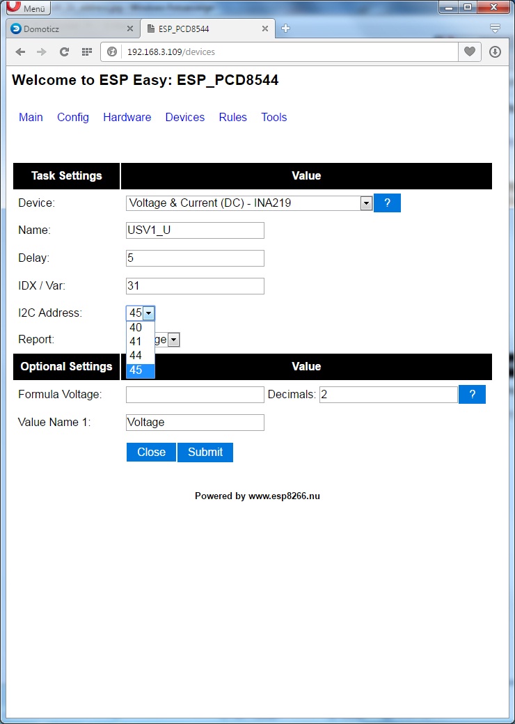
- I2c address option
- INA219_multi_i2c_address.jpg (113.33 KiB) Viewed 11400 times
Please try it and report back.
BR. Adam
Domoticz Beta release on OrangePI PC and BananaPI,
2x RFLink (last version),
ESPEasy, ESPEasy32 (different configurations),
MySensors (different configurations),
2x MiLight RGBW (over RFLink)
and others things

-
miki8989
- New user
- Posts: 3
- Joined: 15 Apr 2016, 08:40
#4
Post
by miki8989 » 15 Jul 2016, 19:07
Hello
I tried it with 2 ina219 and it worked
unfortunately only vedeo the current and power but I see the tension .
I applied as a 12v and load the router
thank you
-
Drum
- Normal user
- Posts: 300
- Joined: 07 Feb 2016, 11:56
#5
Post
by Drum » 15 Jul 2016, 22:32
Is it giving you good numbers for current? The plug in has /1000 on all the value I think, but the library (adafruit) only has it on shunt voltage when calculating load voltage. I think I am getting about 200 ma all the time, but that doesn't seem correct. I have an esp12F, ina219, bme280 and voltage regulator running on 4 AA batteries. Perhaps having the ina219 on the device I am measuring is not the best way to do it..
Any thoughts?
-
Drum
- Normal user
- Posts: 300
- Joined: 07 Feb 2016, 11:56
#6
Post
by Drum » 29 Jul 2016, 10:59
I found something interesting but of course it would need programming, which is something I really need to improve on. It apparently can do the work of 3 separate INA219s with 1 board.
http://www.switchdoc.com/ina3221-breakout-board/
-
XRACE
- New user
- Posts: 1
- Joined: 19 Jan 2017, 21:04
#7
Post
by XRACE » 19 Jan 2017, 21:08
Hi , I was try to compile 2xINA sample and following error appear: 'PLUGIN_DEVICE_ADD' was not declared in this scope
what I am miss?
-
StefanD
- Normal user
- Posts: 21
- Joined: 28 Jan 2017, 20:07
#8
Post
by StefanD » 28 Jan 2017, 20:29
Hi all,
I am trying to measure current and voltage of 24V battery charger using 2xINA sensors. I loaded this modified plugin and connect the 2 sensors, one with address 0x40 and the other with address 0x41 and I can say that it is not working properly. When both sensors are connected it is not possible to read any measurement from them.
When only one it is connected it is not possible to read any measurement if the address is different than 0x40. I hope it helps to find the problem for this plugin.
Best regards
Who is online
Users browsing this forum: Bing [Bot] and 81 guests