Moderators: grovkillen, Stuntteam, TD-er
-
vincen
- Normal user
- Posts: 92
- Joined: 26 Jun 2017, 07:15
#1
Post
by vincen » 06 Jul 2017, 15:20
Hi
Got these sensors
from Amazon
https://www.amazon.com/gp/product/B016Y ... UTF8&psc=1
From my readings in forum I understand I need to setup ESP Easy as input switch for it but I have two questions:
-> what is wiring of such sensors ? have found nothing reliable on Internet

->_some experiences with these same sensors ? as after reading feedback from PIR users in forum looks like a lot of these sensors are really bad...
Thanks
Vincèn
-
Shardan
- Normal user
- Posts: 1156
- Joined: 03 Sep 2016, 23:27
- Location: Bielefeld / Germany
#2
Post
by Shardan » 06 Jul 2017, 16:37
Hello,
the only info i have found is this picture:

- Mini-PIR.jpg (11.93 KiB) Viewed 7265 times
.
To be honest, i'm not sure if it is correct or not.
I did not test these sensors yet so i can't say if they are really reliable or not.
I've used a HC-SR05 (the bigger one) for a server room monitoring, and it works - for me.
I know it does not for others.
Regards
Shardan
Regards
Shardan
-
papperone
- Normal user
- Posts: 497
- Joined: 04 Oct 2016, 23:16
#3
Post
by papperone » 06 Jul 2017, 17:15
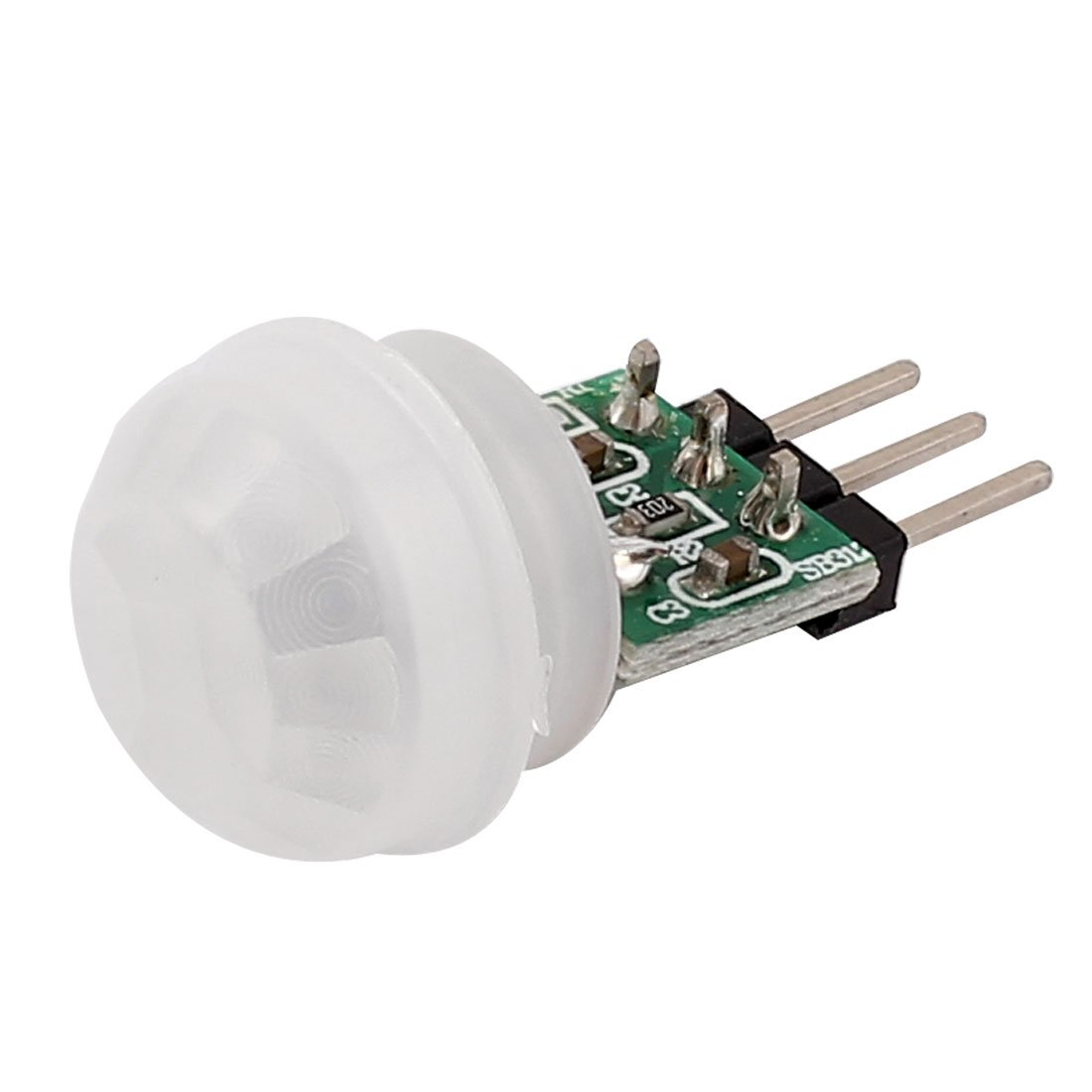
Those shoudl be AS312 PIR (you can check this removing the white plastic and look at the text engraved on the sensor).
then the connection is the one reported by Shardan but please check if the PIR has a voltage regulator as it's supposed to work at 3.3V and not 5V!!
See below the schematic I've found which matches 100% the 5 units I've.

- AS312_cct-1.png (14.5 KiB) Viewed 7262 times
-
Shardan
- Normal user
- Posts: 1156
- Joined: 03 Sep 2016, 23:27
- Location: Bielefeld / Germany
#4
Post
by Shardan » 06 Jul 2017, 18:00
Hello all,
I've just checked the given wiring from my post above with a quick breadboard circuit...
Approved, the pinout is correct.
Regards
Shardan
Regards
Shardan
-
vincen
- Normal user
- Posts: 92
- Joined: 26 Jun 2017, 07:15
#5
Post
by vincen » 07 Jul 2017, 09:09
Shardan wrote: ↑06 Jul 2017, 16:37the only info i have found is this picture:
To be honest, i'm not sure if it is correct or not.
I did not test these sensors yet so i can't say if they are really reliable or not.
I've used a HC-SR05 (the bigger one) for a server room monitoring, and it works - for me.
I know it does not for others.
You are correct, it's correct wiring

papperone wrote: ↑06 Jul 2017, 17:15Those shoudl be AS312 PIR (you can check this removing the white plastic and look at the text engraved on the sensor).
Removed completely the white plastic around the sensor but unhappy nothing engraved or labelled on it
papperone wrote: ↑06 Jul 2017, 17:15then the connection is the one reported by Shardan but please check if the PIR has a voltage regulator as it's supposed to work at 3.3V and not 5V!!
See below the schematic I've found which matches 100% the 5 units I've.
I have checked mine against your schema and I confirm it's wiring on mine so it looks like it has a voltage regulator ! so I guess I can power supply it with the 5V I have on my ESP board no ? and plug signal output to a Digital input and I should be ok with wiring

Thanks for help
Vincèn
-
Shardan
- Normal user
- Posts: 1156
- Joined: 03 Sep 2016, 23:27
- Location: Bielefeld / Germany
#6
Post
by Shardan » 07 Jul 2017, 11:12
Hello,
i've found different data about the Mini PIR.
Most say 2,7...12 V. I doubt about 2,7V as it is lower then the 3,3V output from the small voltage regulator
and would give "bad karma", say instabilities.
Anyways, 5V is safe and should work stable - at least it did for some hours on my breadboard.
Regards
Shardan.
Regards
Shardan
-
Domosapiens
- Normal user
- Posts: 307
- Joined: 06 Nov 2016, 13:45
#7
Post
by Domosapiens » 07 Jul 2017, 22:50
For the
Sensor
https://unusualelectronics.co.uk/downlo ... 6834e7a283
Shows Vdd Type 3V, Min 2.7, Max 3.3V
Maximum rating 3.6V
For the
Module
If you see a chip marked 7533-1 on your module then it has a 3V voltage regulator.
Power supply needs to be higher then 3V (voltage drop is 100mV@1mA) and lower then 24V.
Hope this helps
30+ ESP units for production and test. Ranging from control of heating equipment, flow sensing, floor temp sensing, energy calculation, floor thermostat, water usage, to an interactive "fun box" for my grandson. Mainly Wemos D1.
-
vincen
- Normal user
- Posts: 92
- Joined: 26 Jun 2017, 07:15
#8
Post
by vincen » 08 Sep 2017, 13:26
I confirm that sensor works fine powered at 3.3V by the ESP board
Works like a charm for me

Who is online
Users browsing this forum: No registered users and 1 guest