
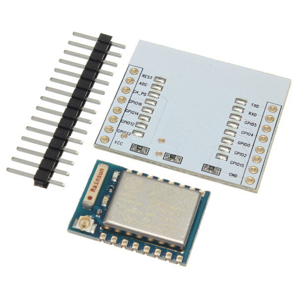
On this style of esp adaptor board, am I safe to assume that the 3 resistors are gpio pull ups / downs for proper boot state?
I can't find a schematic of these boards anywhere, can anyone point me to one?
Thanks,
Brian H.
Moderators: Voyager, BertB, grovkillen, Stuntteam, LisaM

It is my understanding GPIO-O and GPIO-2 need to be pulled on demand only, no ?TD-er wrote: ↑05 Oct 2019, 11:39 If you want to make sure all boot state pins are correctly set, you can also use the ESP-12S.
These have the pull-up (ESP-EN, GPIO-0, GPIO-2) and pull-down (GPIO-15) set.
What does bother me is that these boards apparently have 2 resistors for pull-up/down, so I would expect GPIO-0 and -2 are not set.
See the documentation: https://espeasy.readthedocs.io/en/lates ... on-esp8266iron wrote: ↑05 Oct 2019, 12:41It is my understanding GPIO-O and GPIO-2 need to be pulled on demand only, no ?TD-er wrote: ↑05 Oct 2019, 11:39 If you want to make sure all boot state pins are correctly set, you can also use the ESP-12S.
These have the pull-up (ESP-EN, GPIO-0, GPIO-2) and pull-down (GPIO-15) set.
What does bother me is that these boards apparently have 2 resistors for pull-up/down, so I would expect GPIO-0 and -2 are not set.
-D
I understand all that very well. Just pointing out that ESP-EN pull up and GPIO-15 pull down are mandatory for operation and should be "hard wired". While GPIO-0 and GPIO-2 only need to be pulled conditionally therefore should not be hard wired thus there is not pads for those in that adapter.TD-er wrote: ↑05 Oct 2019, 16:53See the documentation: https://espeasy.readthedocs.io/en/lates ... on-esp8266iron wrote: ↑05 Oct 2019, 12:41It is my understanding GPIO-O and GPIO-2 need to be pulled on demand only, no ?TD-er wrote: ↑05 Oct 2019, 11:39 If you want to make sure all boot state pins are correctly set, you can also use the ESP-12S.
These have the pull-up (ESP-EN, GPIO-0, GPIO-2) and pull-down (GPIO-15) set.
What does bother me is that these boards apparently have 2 resistors for pull-up/down, so I would expect GPIO-0 and -2 are not set.
-D
Some pins should be pulled up or down or else the ESP will not boot properly.
A pull-up or pull-down resistor is meant to just slightly pull its value to some level, but it can be overriden by the ESP itself if needed.
Just make sure the level is well defined during boot.
This also means not all sensors can be connected to all GPIO pins. For example a sensor which pulls a pin to some level may prevent the ESP from booting when connected to one of these pins.
Users browsing this forum: No registered users and 1 guest
