Hi
today I brought in application my ESP32-S2 to detect 2 LED status via LDR. So I connected 2 LDRs to the ESP unit (incl. extra resitor) to make use from the internal analog inputs.
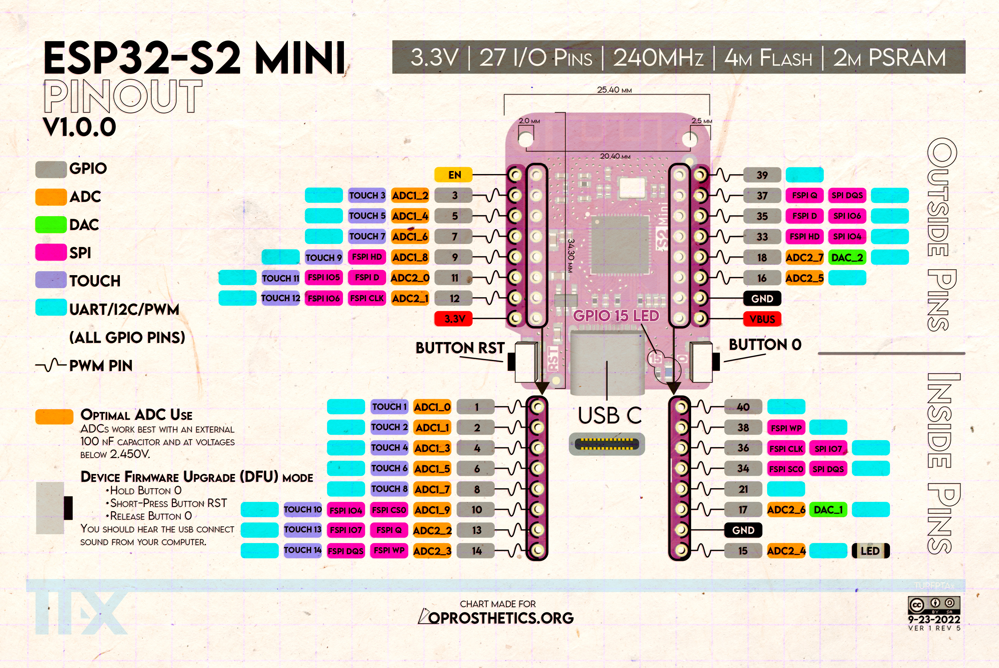
Because of seperation I connected one LDR to the ADC1 and one LDR to the ADC2 but all pins I used so far from ADC1 (eg. GPIO 3, 5 or 7) result into automatic increase and decrease of values without any connection/voltage to these pins. Whats happening?
Can you you please recommend which pins I can make use of for 2 Analog Inputs? Best would be from the outer line because I have only soldered connection pins to the two outer lines.
For ADC2 I am currently using GPIO 18.
Thx
ADC usage of ESP32-S2 Mini
Moderators: grovkillen, Stuntteam, TD-er
Re: ADC usage of ESP32-S2 Mini
First of all, do not use ADC2 pins for analog readings.
ADC2 is used by the WiFi part of the ESP and thus if you try to read from ADC2 while also using WiFi, the readings will be completely useless.
This is on all ESP32 variant as far as I know.
Second, how is the LDR connected to the board?
You need at least one other resistor per LDR.
Typically like this:
3V3 --- R --- GPIO --- LDR ---- GND
What range of resistance is the LDR expected to have?
You can start with a 1k resistor for R, so the current will be limited if the LDR's resistance gets close to 0.
But if the LDR's resistance is much higher, then you might need a higher value for R.
Re: ADC usage of ESP32-S2 Mini
Thx. I have to look up /measure the exact values but this is a full reuse I have already had in operation with an ESP32-Mini but his USB connector got broken so I had to replace this hw and used the S2 mini now.
The voltage level was checked and resistor values claculated before and never above 2V.
So will also reconnect used ADC2 to a ADC1 GPIO but this will lead to another "automatic increase/decrease" result?
The voltage level was checked and resistor values claculated before and never above 2V.
So will also reconnect used ADC2 to a ADC1 GPIO but this will lead to another "automatic increase/decrease" result?
Last edited by Oetsch on 29 Jul 2023, 17:27, edited 1 time in total.
Re: ADC usage of ESP32-S2 Mini
Checked and LDR is 10k to 1M and resistor 10k
rewired to ADC1 only which is GPIO 5 and 7 and still having automatic increase/decrease by each second (cycle time) from 0 till 8191 and backwards.
Re: ADC usage of ESP32-S2 Mini
Thx and found the faulty point. The connection to ground from the resistors was not good so results into free floating voltage.
After 2 seconds fixing the soldering point everything is fine.
Who is online
Users browsing this forum: No registered users and 27 guests