Difference between revisions of "PCF8591"
Jump to navigation
Jump to search
(Nieuwe pagina aangemaakt met '== Toepassing == De ESP is in staat om extra analog ingangen uit te lezen via een I2C AD Converter chip van het type PCF8591. Hieronder vind je een beschrijving hoe...') |
m (→Introductie) |
||
| (11 intermediate revisions by the same user not shown) | |||
| Line 1: | Line 1: | ||
| − | = | + | = Introduction = |
| − | + | The ESP-01 module has no analog input. Only boards like the ESP-07 and ESP-12 break out the single ADC (TOUT) pin on the ESP chip. But we can provide all ESP modules with 4 analog inputs using the PCF8591 I2C ADC chip. | |
| − | == | + | = Hardware = |
| − | + | [[File:PCF8591Module.jpg|320px]] | |
| + | [[File:PCF8591.jpg|320px]] | ||
| − | + | The PCF8591 can be bought on eBay as a bare chip or a plug and play module. | |
| − | |||
| − | + | = Software = | |
| − | |||
| − | |||
| − | |||
| − | == | + | == Custom Sketch == |
| − | + | ||
| + | == ESP Easy == | ||
| + | Use the device tab on the ESP Easy webinterface and create a new task by editing one of the available tasks. Select "PCF8591 Analog input" from the dropdown box. | ||
| + | |||
| + | [[File:EasyConfigPCFA.png]] | ||
| + | |||
| + | Enter the IDX found in the Domoticz device page. Also select the port on the PCF8591 that you want to read (Numbered 0 - 3). That should be all. | ||
| + | |||
| + | === Optional settings === | ||
| + | |||
| + | [[ EasyFormula | Use of formulas]] | ||
| + | |||
| + | [[ EasyValueNames | Use of value names]] | ||
| + | |||
| + | == ESP Connexio == | ||
| + | Command: | ||
''<nowiki>ExtWiredAnalog <poort>, <Variabele></nowiki>'' | ''<nowiki>ExtWiredAnalog <poort>, <Variabele></nowiki>'' | ||
| Line 34: | Line 46: | ||
|} | |} | ||
| − | === | + | === Sample === |
ExtWiredAnalog 1,3 | ExtWiredAnalog 1,3 | ||
| − | |||
| − | |||
Latest revision as of 12:22, 4 October 2015
Contents
Introduction
The ESP-01 module has no analog input. Only boards like the ESP-07 and ESP-12 break out the single ADC (TOUT) pin on the ESP chip. But we can provide all ESP modules with 4 analog inputs using the PCF8591 I2C ADC chip.
Hardware


The PCF8591 can be bought on eBay as a bare chip or a plug and play module.
Software
Custom Sketch
ESP Easy
Use the device tab on the ESP Easy webinterface and create a new task by editing one of the available tasks. Select "PCF8591 Analog input" from the dropdown box.
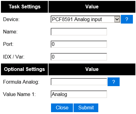

Enter the IDX found in the Domoticz device page. Also select the port on the PCF8591 that you want to read (Numbered 0 - 3). That should be all.
Optional settings
ESP Connexio
Command:
ExtWiredAnalog <poort>, <Variabele>
| Parameter: | Beschrijving: | Bereik: | Opmerking: |
|---|---|---|---|
| Poort | 1 t/m 32 | ||
| Variabele | 1 t/m 15 |
Sample
ExtWiredAnalog 1,3