Power
Introduction
The ESP8266 is not very power hungry, but it requires some special measures to operate in a predictable way and to avoid many spurious reboots.
Most disturbances are caused by problems with the power supply
First some facts:
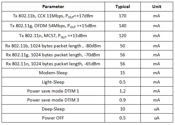

The ESP8266 uses between 50 mA and 170 mA
Since the ESP8266 is transmitting in bursts, it is easy to understand that this behavior will cause a lot of spikes and other undesired signals on the power lines and these can easily translate into unwanted resets and other disturbances. This also pops up when factory made boards like NodeMCU are being used, especially in conjunction with external devices.
What can you do?
1 - First, use a good power supply, capable to deliver 5 volt at 1 Amp.
2 - Mount capacitors across the power lines, as close as possible to the ESP8266.
3 - Mount a 10 nF (multi layer, preferably smd) capacitor from the reset terminal to ground.
4 - Use at least one 10uF (tantalum) and one 100 nF (multi layer) capacitor per externally connected device.
5 - Use a separate power supply to feed external devices.
6 - In some cases it helps to by-pass the diode on the NodeMCU board.
Power supply
The power supply is one of the most neglected components and at the same time one of the most important too in every electronic circuit. It all starts with proper food.
A USB/Serial adapter like the FTDI-adapter can never function as a power supply for a working ESP8266, but you can use it for flashing the ESP. Flashing the ESP only needs a small current.
With breadboards the MB102 breadboard power supply is very useful, two versions are seen, with switch and a smaller one without switch. Both are usable. Be carefully with selecting the AC adapter. Best is to use a 7.5V or 9V adapter. 12V adapters can potentially damage the MB102 board, unregulated adapters can have up to 18V unloaded output which will likely destroy the AMS1117 voltage regulator that has only a Max V-in of 15V. Another reason for malfunctioning is overheating. So preferable do not feed more than 9V DC into the powerplug of MB102. This power supply can easily supply an ESP-board and external circuitry, some sensors and leds up to 500mA. If the regulator chip on the MB102 gets too hot to touch you are either giving it a too high input-voltage or sink too much current from it, or a combination.

The MB102 board can be set to 5V and/or to 3.3V at the same time. So you can feed the ESP8266 board and other low voltage sensors/circuits with 3.3V and use 5V on the other side for powering 5V devices like relays or sensors that need 5V. Take care with outputs from 5V sensors that connect to the ESP8266. Use a voltage divider or a level converter.
Always use some extra capacitors in the power rails of your breadboard. 10 to 100 uF per board is good practice. If you have too little filtering you can end up with a unstable ESP that spontaneous resets more or less often.

USB power supply
If you want to use a USB charger as a power supply, make sure it has a CE marking and delivers enough current. 1 Ampere is the least. Also have a look here http://www.lygte-info.dk/
The Danish guy love to bring all sorts of batteries, power supplies, chargers etc to the test bench, to find out what they are made of and sharing the results with us.
Capacitors
All ESP modules have a 100nF smd capacitor over 3.3 Vdd on-board. This value is only good for suppression of very high frequency noise/spikes of 80/160MHz clock-frequency. This 100nF capacitor is always located near pin 3/4 of the ESP8266 chip. Some modules have extra decoupling capacitors soldered on the module but most have not, you have to add them yourself.
This 100nF cap is much too small to keep the Vcc line clear from all spikes and dips caused by the ESP and external components. Especially switching power supplies (but not only these) generate a lot of noise. An extra capacitor is needed with value between 1uF and 10uF. Preferable a tantalum type because of its excellent high frequency properties. This capacitor can best be placed as close to the module as possible. A good place is between the metal cap over the module and Vcc line. Or between Vcc and Gnd pins on a ESP-01 right on the board. Close to the Vcc pin of the module with short wires is almost as good .
Here 2 example pictures of how a tantalum 2.2uF is soldered on ESP-01 and ESP-07. Also on the ESP-07 is a small cap of 4.7nF  soldered between reset and the case.
location of the 2 pictures:
ESP-01: Capacitor 1
ESP-07: Capacitor 2
A large electrolytic type capacitor of a few hundred uF may be used to smoothen the dips caused by the WiFi transmitting and or 50/60Hz power line ripple. Often this capacitor is already present in the power supply but an extra capacitor is good practice, especially when there are leads between supply and the ESP. The location of this capacitor can be on the power rail of your breadboard or close to the Power supply.
Diode by-pass
Below a part of the schematic of the NodeMCU:

Important to notice is the Diode D1, that is placed to protect the USB port and host from external power supplies. In some cases the diode is not a Schottky diode, which has a much lower forward voltage drop (Vf=0.15 ~ 0.45 volt), but a regular diode that can have a Vf of 0.6 ~ 0.9 (or even higher) volt. The actual Vf depends on the current that flows through the diode. The regulator that makes the required 3.3 volts out of the 5 volt tension from the USB port, also has a voltage drop. An AMS 1117 for example (which is on my Chinese NodeMCU board) can have a Vf of up to 1.3 volt. The SPX3819 in the schematic only needs a typical 0.34 @ 500 mA to regulate the power.
The maths show that 5 - 0.9 - 1.3 = 2,8 volt. This is not enough for the ESP8266 to work with. Even with a schottky diode, it is barely enough.
Therefore, it can help to:
- replace the diode with a schottky type or
- just short circuit the diode, but then
be very careful not to blow up your USB host!
.
USB cables
Use a good quality USB cable with NodeMCU. Preferable a short cable with AWG 24 wires. These cables have much lower voltage drop than USB cables with AWG28 wires. Low quality cables are a potential source of reboots and troubles.