VentusW266
 You may hear some construction noise in the background...
Contents
Introduction
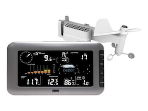
The Plugin for the Ventus W266 is used to connect a Ventus W266 weather station to a home controller like Domoticz. The Ventus W266 is also sold as a RenkForce W205GU.
Hardware
The weather station is delivered with 2 units and a power supply. The outdoor sensor unit is battery powered by 4 AA type batteries. It is recommended to use lithium type batteries so the power is stable during the winter.
The outdoor sensor unit containing the following functions:
- Outdoor temperature
- Outdoor humidity
- Wind direction
- Average wind speed
- Gust wind speed
- Cumulative rainfall
- UV index
- Cumulative number of lightning strikes
- Distance of the nearest lightning strike
The indoor display unit is connected through a wireless 868MHz connection and has the following functions:
- Indoor temperature
- Indoor humidity
- Barometric pressure
- DCF77 clock
The plugin can only read the sensors of the outdoor unit.
CONNECTING THIS PLUGIN WILL VOID THE WARRANTY OF YOUR WEATHER STATION!
Connections
Did we already say that using this plugin VOIDS YOUR WARRANTY? That is because to use this plugin you have to open up your display unit and solder the ESP inside.
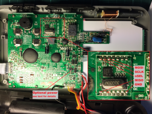
The ESP is connected using 4 GPIO pins. The prototype used an ESP-12E with GPIO pins 4, 5, 12 and 14 and I2C/SPI disabled in the hardware tab of ESP Easy. But all pins are fine, just connect the GPIO lines and specify them when you add the plugin. However it is recommended to avoid using GPIO15 for the nSEL line because the ESP needs GPIO15 to be low at boottime and connecting it to nSEL means it will be high most of the times.
You can click on the image for a full size view of the inside of the display unit and the receiver module and the positions of the connections.
If your ESP module has it's own 3v3 regulator you could connect its power input to the optional power pin specified in the image. But the supplied power supply is not powerful enough to supply both the display with the backlight and an ESP while transmitting. You can exchange the power supply for a USB power supply. The display unit is working fine happy with just the 5 volts.
Be careful when you install the ESP unit. Although the space on the right seems to be perfect for placing the ESP it is close to the indoor temperature sensor and your readings on the display will be off by 2 degrees because of the heat generated by the ESP. A better position is all the way on the left where a bare ESP-12E fits perfect, then you just need to figure out the 3V3 regulator.
When using a bare ESP be sure to apply the ~10K pull up resistors to CH_PD (CD_EN), GPIO0 and a pull down to GPIO15 for stable performance.
It is at the moment not possible to read the indoor sensors using the plugin nor is it in development or planned.

