Page 1 of 1
Ansluta ERROR
Posted: 24 Jan 2017, 16:28
by ayasystems
Hi
As you can see when i try to activate ansluta the rflink is not responding more
20;00;Nodo RadioFrequencyLink - RFLink Gateway V1.1 - R44;
10;version;
10;status;
~~10;version;
20;01;VER=1.1;REV=45;BUILD=09;
10;status;
20;02;STATUS;setRF433=ON;setNodoNRF=OFF;setMilight=OFF;setLivingColors=OFF;setAnsluta=OFF;setGPIO=OFF;setBLE=OFF;setMysensors=OFF;
10;version;
20;03;VER=1.1;REV=45;BUILD=09;
10;status;
20;04;STATUS;setRF433=ON;setNodoNRF=OFF;setMilight=OFF;setLivingColors=OFF;setAnsluta=OFF;setGPIO=OFF;setBLE=OFF;setMysensors=OFF;
10;setAnsluta=on;
20;00;Nodo RadioFrequencyLink - RFLink Gateway V1.1 - R45;
10;status;
10;status;
After it I need clean the eeprom, burn Rflink firmware again and then it is working until i try to activate ansluta again.
Re: Ansluta ERROR
Posted: 24 Jan 2017, 16:43
by ayasystems
Another bug
When you press Ansluta button in RFLinkLoader v1.09 program the command sent to Rflink is:
10;setBLE=off;
Re: Ansluta ERROR
Posted: 24 Jan 2017, 16:58
by Stuntteam
Wil lcheck the loader..
If rflink locks up like in your log, the cc2500 module is either missing, not connectecd correctly, not working or is dead.
Make sure there is enough power and wiring is correct including proper level shifting.
Re: Ansluta ERROR
Posted: 24 Jan 2017, 22:29
by ayasystems
I understand
Could be posible check if it ia working and avoid lock it?
The onky way to restore rflink is flashing an arduino probkam to erase the eprom and then flash again rflink
Regards
Re: Ansluta ERROR
Posted: 25 Jan 2017, 00:28
by Stuntteam
With R45 you can simply connect a wire between pins 12 and 13, reboot rflink, remove wire, reboot again and allsettings are gone.. that works..
Re: Ansluta ERROR
Posted: 27 Jan 2017, 22:34
by Dr_Genestealer
I found if you send "10;setAnsluta=on;" with no CC2500 attached you get one response (see below) but then nothing, even when restarting the board.
I get the same "bug" when the CC2500 is connected. I believe the wiring is correct and the CC2500 is good. I have tried wiring with 10Ks on each line, with two types and level shifters and even wired direct (3.3V VCC still for power)
You have to reset the board by shorting the PWM 13 and 12 pins and restarting the board, to clear the settings.
Debug log:
Code: Select all
10;status;
20;03;STATUS;setRF433=ON;setNodoNRF=OFF;setMilight=OFF;setLivingColors=OFF;setAnsluta=OFF;setGPIO=OFF;setBLE=OFF;setMysensors=OFF;
10;setAnsluta=on;
20;00;Nodo RadioFrequencyLink - RFLink Gateway V1.1 - R45;
10;status;
10;status;
I know my CC2500 is working and just tried it with "Ansluta-Remote-Controller" from
https://github.com/NDBCK/Ansluta-Remote-Controller (Although with that code I had the CC2500 Pin 8 = (CS) connected to the MEGA Pin 53, rather than the Pin 47 as per RF LINKs documentation.
Just as a note, I'm using an Arduino Mega 2560 and CC2500 with a TXB0108 logic level converter.
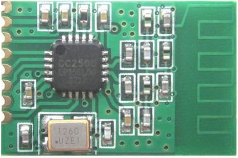
Photo of the CC2500 I'm using (linked from
http://www.nemcon.nl/blog2/wiring):
 I have observed some strange behaviour:
Steps to reproduce:
- Clear EEPROM or re-load firmware.
With no CC2500 connected, send "10;setAnsluta=on;".
Responce back: "20;00;Nodo RadioFrequencyLink - RFLink Gateway V1.1 - R45;".
RF Link has now hung and will not respond. E.G. "10;status;" get no response to further commands. Only the reset button will elicit the following: "20;00;Nodo RadioFrequencyLink - RFLink Gateway V1.1 - R45;".
Directly, without level shifting, connect Pin 3 = (MOSI) = MEGA Pin 51, Pin 4 = (SCK) = MEGA Pin 52, Pin 5 = (MISO) = MEGA Pin 50 and Pin 8 = (CS) = MEGA Pin 47, to the CC2500.
Spontaneously, the following is received: "20;01;setAnsluta=OFF;NO CC2500;".
With the CC2500 still connected, re-sending "10;setAnsluta=on;" will elicit the same response: "20;00;Nodo RadioFrequencyLink - RFLink Gateway V1.1 - R45;" and "20;01;setAnsluta=OFF;NO CC2500;".
Repowering/resetting the board also elicits the same response:
Code: Select all
20;00;Nodo RadioFrequencyLink - RFLink Gateway V1.1 - R45;
20;01;setAnsluta=OFF;NO CC2500;
20;00;Nodo RadioFrequencyLink - RFLink Gateway V1.1 - R45;
20;01;setAnsluta=OFF;NO CC2500;
Full copy of log:
Code: Select all
20;00;Nodo RadioFrequencyLink - RFLink Gateway V1.1 - R45;
10;version;
20;01;VER=1.1;REV=45;BUILD=09;
10;status;
20;02;STATUS;setRF433=ON;setNodoNRF=OFF;setMilight=OFF;setLivingColors=OFF;setAnsluta=OFF;setGPIO=OFF;setBLE=OFF;setMysensors=OFF;
10;setAnsluta=on;
20;00;Nodo RadioFrequencyLink - RFLink Gateway V1.1 - R45;
20;01;setAnsluta=OFF;NO CC2500;
Any ideas?
Richard
Re: Ansluta ERROR
Posted: 27 Jan 2017, 22:45
by Dr_Genestealer
ayasystems wrote:Another bug
When you press Ansluta button in RFLinkLoader v1.09 program the command sent to Rflink is:
10;setBLE=off;
I think you mean in RFLink Loader V1.09, when you press the "Ansluta: OFF" button, the "10;setBLE=off;" command is sent, this is incorrect.
Re: Ansluta ERROR
Posted: 02 Feb 2017, 23:49
by ayasystems
Exactly... my definition of the bug was very bad
Thanks man
Re: Ansluta ERROR
Posted: 03 Feb 2017, 00:28
by Stuntteam
TXB0108 is not working..
we are i nthe process of testing a number of level shifters and will post details soon.
Re: Ansluta ERROR
Posted: 04 Feb 2017, 02:08
by Dr_Genestealer
Hi Stuntteam,
Any ideas on my full post above about the locking up of the firmware, seems a bit strange?
It's also odd that the TXB0108 is not working for you, it is working for me with other arduino software, just not with the RFLink firmware.
I have also tried BSS138 Bi-directional level converters with RFLink but with no success.
Photo of my working setup with aforementioned "Ansluta-Remote-Controller" software.


Re: Ansluta ERROR
Posted: 18 Feb 2017, 18:01
by Redfeather
I have the same issue. For whatever reason I had it (24TRGC2 ) working once when I upgraded from 44 to 45. I was able to receive the Philips LivingColors Gen1 commands and I was able to send commands to which the Philips LivingColors Gen1 light responded. However I can't get it working any more.
What i do think is that either;
- A. The RFLink is either extremely picky on timing.
B. That an reset loop for the CC2500/24TRGC2 is not implemented correctly.
However I can't find the sourcecode anywhere. For now I am a little bit disappointed

that after 2 hours of soldering and debugging the result is

-----
Please let me know what I can do in order to assist in debugging / developing
Re: Ansluta ERROR
Posted: 21 Feb 2017, 17:29
by Stuntteam
The wiring page has been updated with some level shifters that I have tested and that work.
This means that you connect the 5 volt side to the mega pins as listed and the 3 volt side to the cc2500 as listed.
This means that the level shifter fits inbetween the mega and the cc2500.
For the listed modules no additional hardware is needed.
Dr_Genestealer wrote:It's also odd that the TXB0108 is not working for you, it is working for me with other arduino software, just not with the RFLink firmware.
I have tested the TXB0108 (actually received TXB while ordering TXS) made some code changes etc. and now it seems to work more reliable.
In your photos it shows that you are using an additional power converter. That could help but I am not using it.
However, there seem to be plenty of issues with the TXB reading this:
http://forum.arduino.cc/index.php?topic=262104.0 and other threads
Re: Ansluta ERROR
Posted: 22 Feb 2017, 16:25
by Dr_Genestealer
Hey Guys,
That's great, thank you for adding the extra detail. I will give it a go with the added instructions. I also have another CC2500 to try.
I will give it a go with the latest rfl4607_tst.zip (REV=46, BUILD=07) or is Build 06 the best to test?
Also, I see Rev 46 is not officially on the web page yet?
Re: Ansluta ERROR
Posted: 22 Feb 2017, 17:22
by Stuntteam
Rev 46 will be public soon.
Re: Ansluta ERROR
Posted: 25 Feb 2017, 15:06
by Redfeather
Stuntteam wrote:Rev 46 will be public soon.
On a funny note:
I am ready

Bryan Adams - I'm Ready
https://goo.gl/ZZ2ezy (Youtube Link)
On a more serious note:
Is there an ETA for the Rev 46?
Re: Ansluta ERROR
Posted: 01 Jun 2017, 12:34
by techsoz
hi there,
I am a newby. I bought an arduino mega, and an nodo rf link 868 kit. also bought a NRF24L01+ module because i thought it might control my ikea omlopp/ansluta setup. It is soldered an fits together neatly.
I assume I was wrong there with the ansluta however.
So I am getting an cc2500 and some level shifterts now. I found some wiring, but this seems to be more complicated than i thought. Do I need the rf link modle at all
how do i connect the cc2500 wo the whole thing, as some of the ports stated here
http://www.nemcon.nl/blog2/wiring (under cc2500) are blocked by my rflink module
(47...53) .
SO can I use only one of toth, rflink 858 or cc2500, or how do i wire both of them?
I found some wiring here:
https://github.com/Genestealer/Home-Ass ... ay-ESP8266 but I am more condused than before. what is all this!?
please point me to easy ressources if possible (i searched some other forums unsuccessuflly). I am a beginner, so I might miss out some basic principoles.
thank you.
rene


