Page 1 of 1
electrical power outage detection
Posted: 16 Sep 2019, 15:55
by Gilles
During our summer vacations far from home, there has been an electrical power outage in the house.
I had detected that there was no more internet access to the house but no way to know if it was because of the Internet box. At the end I have called a neighbor but it was too late for the freezer, so we have had to throw away a lot of frozen food.
So I was thinking... I have a 4G Huawei router which can run sometime on battery if there is an electrical power outage. I was thinking to use it to have a wifi connection to Internet to send a mail.
The question now is how to detect a electrical power failure with ESPEASY? I have an ESP07S that I could use to connect to a battery. I could use the deepsleep feature but how to detect the outage (sensor) to boot the espxxx, connect to the wifi and send a mail (or sms) then go back to sleep.
Any tip or suggestion is welcomed.
Gilles
Re: electrical power outage detection
Posted: 16 Sep 2019, 16:04
by TD-er
You could let an LED run on some 5V power adapter and have the LED of an optocoupler in series with that LED.
The transistor side of the optocoupler could then be used to trigger something on the ESP (or even boot it, if it is put to deep sleep)
Re: electrical power outage detection
Posted: 17 Sep 2019, 09:41
by Gilles
Thanks TD-er, good idea.
I am not an electronic specialist, so I will try to ask around some friends. My understanding is that when there is a power outage, it closes a second circuit which can be used with the deepsleep feature to awake the espxxx.
Re: electrical power outage detection
Posted: 17 Sep 2019, 11:38
by Wiki
Other idea: Take a relay "NC" (normally closed), powered by the power circuit of your freezer to connect the battery of your ESP on power loss.
Re: electrical power outage detection
Posted: 19 Sep 2019, 17:22
by Gilles
Hi TD-er,
I went through some doc on the optocouplers.
In your example,in a normal case, when there is no electrical power cut, the optocoupler LED will close the (power) circuit on which the esp (deepmode) is connected to.
AND It will open the power circuit when there is an electrical power outage.
I think that if I want to awake an esp in deepsleep mode, I need the power circuit to be closed only when there is an electrical power cut. So, the opposite.
What do you think?
any diagram would be really helpful to me.
Thanks
Gilles
Re: electrical power outage detection
Posted: 19 Sep 2019, 18:01
by grovkillen
NO = normal open
NC = normal close
So there's two different types (and sometimes one relay have both options) so your use case is covered.
Re: electrical power outage detection
Posted: 20 Sep 2019, 09:37
by TD-er

See
here for more explanation on the difference between NPN and PNP transistors and which one to use to "invert" the signal.
The transistor part of an optocoupler is just a normal transistor. So they are available in PNP and NPN configuration.
In Dutch we have the line "Pijl Naar Plaat" to remember which one is which. (Pijl = arrow, Naar = to, Plaat = plate)
So PNP is the one with the arrow pointing to the plate in the schematic symbol.
Not sure if there is such a helper to remember it in English.
Re: electrical power outage detection
Posted: 20 Sep 2019, 09:40
by Gilles
Herer is the simple diagram I am thinking of, based on TD-er suggestion.
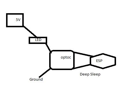
- optocoupler.jpg (15.73 KiB) Viewed 18527 times
Re: electrical power outage detection
Posted: 20 Sep 2019, 09:42
by Gilles
oops , sorry I have added my post at the same time as yours .
Thanks
Gilles
Re: electrical power outage detection
Posted: 20 Sep 2019, 09:47
by TD-er
Don't forget the resistor in series with the LEDs.
Also take into account the voltage drop of a LED, which differs for different colors.
I assume the LED used in the optocoupler is a "red" one, so then the voltage drop is about 1.8V
If you add a LED with a different color, its voltage drop may be higher.
Placing them in series will cause a drop equal to the some of both voltage drops.
So you may need to experiment with some resistor values first to make sure the current through the LEDs is not too high.
It should be no more than 20 mA and some LEDs used in optocouplers even require less. (check data sheet)
The 2nd LED is only for debugging purposes so you can see it should be on or off.
Considering you're using only 5V for this, you may want to place both LEDs parallel, each with their own resistor, but then you must make sure to check there is some current flowing through the optocoupler LED (measure voltage over resistor, it should be 5V - 1.8V if the LED is on and 0V if the LED is off)
Re: electrical power outage detection
Posted: 22 Sep 2019, 14:57
by Gilles
Based on your example, and as I have more than a lack of knowledge in electronics, I have searched the web and I have found this (sorry in french) diagram:

- detection-du-secteur-230v.jpg (25.92 KiB) Viewed 18368 times
.
OUTPUT: 0V if electricity exists and 3,3V if cut
The point is that the esp will receive 3,3V when the electrical power is cut and this until it is back.
My idea is that the esp awakes, connects to the wifi, sends a mail and then go back to deepsleep.
In this case what would be the esp (deepsleep) behaviour if the cut lasts 2 days ? Will it deepsleep then awake then deepsleep again then awake etc...?
Ideally the esp should receive 3,3V during lets say 10sec to trigger the awake then stops.
Re: electrical power outage detection
Posted: 22 Sep 2019, 17:20
by Shardan
Just a very simple idea I had for this purpose.
Just pull up the GPIO 16 (Deepsleep) with a 10K resistor - let it sleep until triggered, then run once and get back to sleep.
For triggering the reset input can be used with a relay and some addon parts.
.
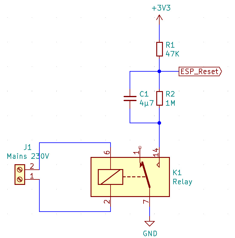
- Powerloss_detection.jpg (83.94 KiB) Viewed 18352 times
.
The relay uses the "normally closed" contact, so as long as 230V~ is there the contact is open.
R1 (47K) pulls up the reset so the ESP goes to deepsleep and stays there.
Deepsleep must be configured to "deepsleep forever" so the ESP doesn't start up periodically.
If power fails the relay contact closes. The capacitor C1 (4µ7) pulls down the ESP reset for a short timespan.
ESP starts, sends message and goes to deepsleep again.
As the capacitor is loaded and does not pull down reset permanently nothing more will happen until mains voltage returns.
At the moment mains returns the relay opens the contact. R2(1M) unloads the capacitor - ready for a new round.
BTW - I'd use a 100K-Resistor of around 2 Watt at least for the opto circuit - the whole optocoupler circuit takes up around 1,15 Watt
and most of it is just "burned" on the resistor. 1 Watt might be a bit too small.....
And 1,15Watt isn't much less then a relay.
Re: electrical power outage detection
Posted: 23 Sep 2019, 08:51
by Gilles
Hi Sherdan,
so the 100K-Resistor of around 2 Watt has to be connected between the main 230V and the optocoupler right ? Between 2 and 6 or between 1 and 2 ?
I hope to go to the shop this week. I will ask for an optocoupler with a "normally closed" relay.
Re: electrical power outage detection
Posted: 23 Sep 2019, 11:15
by TD-er
The relay used by Shardan is a 230 V version, so then you don't need extra components.
I don't like the idea of having a single resistor burning away energy just to power an LED through mains.
Also 230V over 100k is a current of 2.3 mA.
I wonder is that's enough for the LED in the optocoupler to light up enough.
There is a small capacitor over the LED (and the reversed diode to protect the LED in the optocoupler) to keep the voltage over the LED stable.
But still it is a half-period signal over the LED, so it may fluctuate.
There is a larger capacitor over the transistor part of the optocoupler, which will stabilize the value, but when the LED switches off, the voltage over C2 is then rising very slow and I don't think that's a good "wake up" signal for the ESP.