help to use a PME for input switch

Moderators: grovkillen, Stuntteam, TD-er

Post Reply
Message
Author
reza
Normal user
Posts: 88
Joined: 13 Jun 2017, 21:14

help to use a PME for input switch

#1 Post by reza » 16 Jun 2017, 09:43

hi
there is a problem with PME input switch. i want when key was 0 or 1 so send a message on/off to domoticz and dummy switch in domoticz go to on/off.
but when in device i select a PME with this setting:
name : key_1
enable : on
port : 10
port type : digital
delay : "i want set to 0 but dont permission to set and auto set 60!"
send to controll :no
idx : 0
1 - value - no Formula - 2

so when set delay to 60s so after change switch have 60s delay.when i change to to 1 or 2s and this rule send every 1s ...

Code: Select all

on key_1#value do
if [key_1#value]=1
SendToHTTP 192.168.1.200,8080,/json.htm?type=command&param=switchlight&idx=100&switchcmd=On
else
SendToHTTP 192.168.1.200,8080,/json.htm?type=command&param=switchlight&idx=100&switchcmd=Off
endif
endon
please help i need to this input key with PME

User avatar
grovkillen
Core team member
Posts: 3621
Joined: 19 Jan 2017, 12:56
Location: Hudiksvall, Sweden
Contact:

Re: help to use a PME for input switch

#2 Post by grovkillen » 16 Jun 2017, 09:54

Default delay value is set on the config page:
https://www.letscontrolit.com/wiki/inde ... onfig_page
There's the default 60 seconds. You may change this to 1 here, or just use 1 in the device settings.

IDX value should not be 0, just use any other value (1 for example). More information found on wiki.
https://www.letscontrolit.com/wiki/inde ... vices_page


You should always provide a screenshot of the settings for easier understanding. And try to use the wiki as much as possible. Report missing information/guides here on the forum and we'll add them to the wiki.
ESP Easy Flasher [flash tool and wifi setup at flash time]
ESP Easy Webdumper [easy screendumping of your units]
ESP Easy Netscan [find units]
Official shop: https://firstbyte.shop/
Sponsor ESP Easy, we need you :idea: :idea: :idea:

reza
Normal user
Posts: 88
Joined: 13 Jun 2017, 21:14

Re: help to use a PME for input switch

#3 Post by reza » 16 Jun 2017, 11:01

grovkillen wrote: 16 Jun 2017, 09:54 Default delay value is set on the config page:
https://www.letscontrolit.com/wiki/inde ... onfig_page
There's the default 60 seconds. You may change this to 1 here, or just use 1 in the device settings.

IDX value should not be 0, just use any other value (1 for example). More information found on wiki.
https://www.letscontrolit.com/wiki/inde ... vices_page


You should always provide a screenshot of the settings for easier understanding. And try to use the wiki as much as possible. Report missing information/guides here on the forum and we'll add them to the wiki.
very thanks friend for answer me . my problem is not setting of delay...
this in photo is all my setting. when i set a device (PME for input switch) so in log , depending on delay time (for example 1s) send every second a message to log state of key. when create a rule for send to controller so every second send state to controller also when light off with domoticz after 1second again send state of key and trun on light...
i want just send one message until when change state of key.
please help :( i am confused
kdkkddk.jpg
kdkkddk.jpg (292.88 KiB) Viewed 15017 times

papperone
Normal user
Posts: 497
Joined: 04 Oct 2016, 23:16

Re: help to use a PME for input switch

#4 Post by papperone » 16 Jun 2017, 11:48

I think the PME plugin has been designed like this, not sure why, maybe someone with more knowledge can comment...
By the way, if you want to make delay "optional" (so bring it to 0 will disable it) you need to modifiy the plugin and compile the binary by yourself.
My TINDIE Store where you can find all ESP8266 boards I manufacture --> https://www.tindie.com/stores/GiovanniCas/
My Wiki Project page with self-made PCB/devices --> https://www.letscontrolit.com/wiki/inde ... :Papperone

reza
Normal user
Posts: 88
Joined: 13 Jun 2017, 21:14

Re: help to use a PME for input switch

#5 Post by reza » 16 Jun 2017, 16:27

papperone wrote: 16 Jun 2017, 11:48 I think the PME plugin has been designed like this, not sure why, maybe someone with more knowledge can comment...
By the way, if you want to make delay "optional" (so bring it to 0 will disable it) you need to modifiy the plugin and compile the binary by yourself.
thank you friend for answer. now i dont know , what am i do :( friends please help :(
you told if i change delay to 0 so this problem solve ? how change delay to 0 ?because in device setting i can not set 0. must more than 0.

papperone
Normal user
Posts: 497
Joined: 04 Oct 2016, 23:16

Re: help to use a PME for input switch

#6 Post by papperone » 16 Jun 2017, 17:48

reza wrote: 16 Jun 2017, 16:27
papperone wrote: 16 Jun 2017, 11:48 I think the PME plugin has been designed like this, not sure why, maybe someone with more knowledge can comment...
By the way, if you want to make delay "optional" (so bring it to 0 will disable it) you need to modifiy the plugin and compile the binary by yourself.
thank you friend for answer. now i dont know , what am i do :( friends please help :(
you told if i change delay to 0 so this problem solve ? how change delay to 0 ?because in device setting i can not set 0. must more than 0.
Yes this is what I said, PME plugin has been designed with the field "Delay" mandatory, so you cannot enter zero!
My TINDIE Store where you can find all ESP8266 boards I manufacture --> https://www.tindie.com/stores/GiovanniCas/
My Wiki Project page with self-made PCB/devices --> https://www.letscontrolit.com/wiki/inde ... :Papperone

reza
Normal user
Posts: 88
Joined: 13 Jun 2017, 21:14

Re: help to use a PME for input switch

#7 Post by reza » 16 Jun 2017, 19:54

papperone wrote: 16 Jun 2017, 17:48
reza wrote: 16 Jun 2017, 16:27
papperone wrote: 16 Jun 2017, 11:48 I think the PME plugin has been designed like this, not sure why, maybe someone with more knowledge can comment...
By the way, if you want to make delay "optional" (so bring it to 0 will disable it) you need to modifiy the plugin and compile the binary by yourself.
thank you friend for answer. now i dont know , what am i do :( friends please help :(
you told if i change delay to 0 so this problem solve ? how change delay to 0 ?because in device setting i can not set 0. must more than 0.
Yes this is what I said, PME plugin has been designed with the field "Delay" mandatory, so you cannot enter zero!
so is not there any way for this issue ? :( this is very bad that we can not use extender gpio for input switch :(

Shardan
Normal user
Posts: 1156
Joined: 03 Sep 2016, 23:27
Location: Bielefeld / Germany

Re: help to use a PME for input switch

#8 Post by Shardan » 16 Jun 2017, 19:59

If you need just switch inputs you may use a PCF8574 as GPIO extender.
Regards
Shardan

reza
Normal user
Posts: 88
Joined: 13 Jun 2017, 21:14

Re: help to use a PME for input switch

#9 Post by reza » 17 Jun 2017, 00:41

but input switch and relay have some bug generally . for example when define a input key with send to controller and define a relay (and define on/off command in domoticz) so if you send a on/off quick( i mean light on and fast off , or light off and fast on with key or domoticz, so relay is on/off several times and stop. i think this is a bug. i want report this to espeasy team. how do report this?

User avatar
grovkillen
Core team member
Posts: 3621
Joined: 19 Jan 2017, 12:56
Location: Hudiksvall, Sweden
Contact:

Re: help to use a PME for input switch

#10 Post by grovkillen » 17 Jun 2017, 08:17

What do you mean, do the (in your example) relay turn on and off more times than you have pressed the switch? If the relay is turned on and off equal number of times as you have pressed the switch I do not see it as a bug.

If the behavior is not wanted you should either file for an enhancement for a delay (for filtering out multiple fast switch changes) or make your own rule for it. The later is of implemented at your own pace.
ESP Easy Flasher [flash tool and wifi setup at flash time]
ESP Easy Webdumper [easy screendumping of your units]
ESP Easy Netscan [find units]
Official shop: https://firstbyte.shop/
Sponsor ESP Easy, we need you :idea: :idea: :idea:

reza
Normal user
Posts: 88
Joined: 13 Jun 2017, 21:14

Re: help to use a PME for input switch

#11 Post by reza » 17 Jun 2017, 14:13

grovkillen wrote: 17 Jun 2017, 08:17 What do you mean, do the (in your example) relay turn on and off more times than you have pressed the switch? If the relay is turned on and off equal number of times as you have pressed the switch I do not see it as a bug.

If the behavior is not wanted you should either file for an enhancement for a delay (for filtering out multiple fast switch changes) or make your own rule for it. The later is of implemented at your own pace.
i am set up a strange things :) for my needs
i need a local fast key and i need extend GPIO also i need send of relay state to domoticz and receive from domoticz and action relay also a Synchronized between toggle switch and domoticz action.
for this i use a arduino pro mini for PME and in sketch of arduino add a local key :

Code: Select all

  stateA = digitalRead(relayPinA);
  debouncerA.update();
  int valueA = debouncerA.read();
  if (valueA != oldValueA) {
    digitalWrite(relayPinA, !stateA);
    oldValueA = valueA;
  }
now without connection and nodemcu i can work with key(for when connection have problem) but state of relay dont send to nodemcu and send to domoticz. so i do other things. i connect a wire from relay gpio (arduino) to nodemcu(gpio for input switch) so when relay is on gpio of nodemcu is on and when relay is off so gpio of nodemcu is off. now when i light on with local key and turn on relay so turn on input switch so send a message to domoticz and i see light is on . also when send a message from domoticz so relaycan on and off. so all my need is ok . but there is just a problem.when i work slow and with a 2s delay for on/off one light, all of things is ok (slow for action on/off with domoticz). or on/off with key. but when i turn on and quick turn off(with key or domoticz.quick trun on/turn off) so there is a LOOP and relay start to on/off/on/off/on/off... i thing this is related to delay and Lack of coordination between relay and input key with wire.all of things is ok just this loop is my problem. any body have any idea ?

or instead of this work , can i use a rule for send state of relay(gpio from pme(EXTGPIO)) to domoticz directlly ?

User avatar
grovkillen
Core team member
Posts: 3621
Joined: 19 Jan 2017, 12:56
Location: Hudiksvall, Sweden
Contact:

Re: help to use a PME for input switch

#12 Post by grovkillen » 17 Jun 2017, 22:55

You can use rules for that.

Try here for starter: https://www.letscontrolit.com/wiki/inde ... rial_Rules
ESP Easy Flasher [flash tool and wifi setup at flash time]
ESP Easy Webdumper [easy screendumping of your units]
ESP Easy Netscan [find units]
Official shop: https://firstbyte.shop/
Sponsor ESP Easy, we need you :idea: :idea: :idea:

reza
Normal user
Posts: 88
Joined: 13 Jun 2017, 21:14

Re: help to use a PME for input switch

#13 Post by reza » 18 Jun 2017, 00:52

grovkillen wrote: 17 Jun 2017, 22:55 You can use rules for that.

Try here for starter: https://www.letscontrolit.com/wiki/inde ... rial_Rules
i read this before. and problem is related to this . for the use rule i have to create a promini extender device. for example a digital device with X port.i have to set a delay and if select box of send to controller with a idx so device send value after delay time every time. if i remove select of box and if use a rule , again after delay time,device send to controller again and again(state of relay or key).sorry for my english but do you understand me ? or explain more ?i have a relay on EXTGPIO,2 and i want when EXTGPIO,2 have a change state so "one message" send to domoticz and i can see state of this EXTGPIO on domoticz.

reza
Normal user
Posts: 88
Joined: 13 Jun 2017, 21:14

Re: help to use a PME for input switch

#14 Post by reza » 18 Jun 2017, 09:31

grovkillen wrote: 17 Jun 2017, 22:55 You can use rules for that.

Try here for starter: https://www.letscontrolit.com/wiki/inde ... rial_Rules
this is a problem that we can not use PME pins for input switch ! is that true ?
also if we can send state of output (relay) in rule so that is very good.for example :
if gpio,2 =1
so send to http....
but now i think just input device can use in if in rule...

User avatar
grovkillen
Core team member
Posts: 3621
Joined: 19 Jan 2017, 12:56
Location: Hudiksvall, Sweden
Contact:

Re: help to use a PME for input switch

#15 Post by grovkillen » 18 Jun 2017, 10:47

You could use the switch#status to control both gpio and publish with rule.

You could maybe provide full setup with screenshots so we might provide real rule code?
ESP Easy Flasher [flash tool and wifi setup at flash time]
ESP Easy Webdumper [easy screendumping of your units]
ESP Easy Netscan [find units]
Official shop: https://firstbyte.shop/
Sponsor ESP Easy, we need you :idea: :idea: :idea:

reza
Normal user
Posts: 88
Joined: 13 Jun 2017, 21:14

Re: help to use a PME for input switch

#16 Post by reza » 18 Jun 2017, 12:59

grovkillen wrote: 18 Jun 2017, 10:47 You could use the switch#status to control both gpio and publish with rule.

You could maybe provide full setup with screenshots so we might provide real rule code?
thank you for help, but i have not any special setup. i have a arduino pro mini for PME. i setup GPIO 4-5 for I2C and this is ok .
in domoticz set up for a dummy switch:
http://192.168.1.123/control?cmd=EXTGPIO,2,0
http://192.168.1.123/control?cmd=EXTGPIO,2,1
and work well(when i send from controller to relay)
but i want , when relay was on with a switch(in arduino pro mini) so send a status (status of relay) to controller and that dummy switch in domoticz go to on/off. just this.

now if i create a "promini extender" switch in "devices" and use this for report ( or use this for rules) so after the delay time , send to controller again and again always .
so i can not use "switch#status"
i must use a command similar to this : EXTGPIO,2#status ! have we a command similar to this ?

in generally how i can send status of a PME gpio to controller (that gpio is use for relay)?

reza
Normal user
Posts: 88
Joined: 13 Jun 2017, 21:14

Re: help to use a PME for input switch

#17 Post by reza » 18 Jun 2017, 13:17

You think , i want use that gpio (arduino pro mini) for a binary sensor. so how send status of binary to controller , after trigger binary ?

User avatar
grovkillen
Core team member
Posts: 3621
Joined: 19 Jan 2017, 12:56
Location: Hudiksvall, Sweden
Contact:

Re: help to use a PME for input switch

#18 Post by grovkillen » 18 Jun 2017, 15:20

So you're​ using ArduinoEasy?
ESP Easy Flasher [flash tool and wifi setup at flash time]
ESP Easy Webdumper [easy screendumping of your units]
ESP Easy Netscan [find units]
Official shop: https://firstbyte.shop/
Sponsor ESP Easy, we need you :idea: :idea: :idea:

reza
Normal user
Posts: 88
Joined: 13 Jun 2017, 21:14

Re: help to use a PME for input switch

#19 Post by reza » 18 Jun 2017, 17:45

grovkillen wrote: 18 Jun 2017, 15:20 So you're​ using ArduinoEasy?
what is arduino easy ? i dont know ? i am using espeasy with a PME . connect a arduino promini to nodemcu.

User avatar
grovkillen
Core team member
Posts: 3621
Joined: 19 Jan 2017, 12:56
Location: Hudiksvall, Sweden
Contact:

Re: help to use a PME for input switch

#20 Post by grovkillen » 18 Jun 2017, 19:22

Sorry, read that wrong.
ESP Easy Flasher [flash tool and wifi setup at flash time]
ESP Easy Webdumper [easy screendumping of your units]
ESP Easy Netscan [find units]
Official shop: https://firstbyte.shop/
Sponsor ESP Easy, we need you :idea: :idea: :idea:

reza
Normal user
Posts: 88
Joined: 13 Jun 2017, 21:14

Re: help to use a PME for input switch

#21 Post by reza » 18 Jun 2017, 20:13

grovkillen wrote: 18 Jun 2017, 19:22 Sorry, read that wrong.
now what am i do? :( i think with change of sketch of espeasy we can ...
i want just we can send status of relay to controller ( relay that use a PME ) .when one gpio for example gpio 2 of arduino promini go to 1 so send 1 to controller and when 0 so send 0 to domoticz controller...

User avatar
grovkillen
Core team member
Posts: 3621
Joined: 19 Jan 2017, 12:56
Location: Hudiksvall, Sweden
Contact:

Re: help to use a PME for input switch

#22 Post by grovkillen » 18 Jun 2017, 20:29

reza wrote: 18 Jun 2017, 20:13 ...
I say this once more:

You could maybe provide full setup with screenshots so we might provide real rule code?
ESP Easy Flasher [flash tool and wifi setup at flash time]
ESP Easy Webdumper [easy screendumping of your units]
ESP Easy Netscan [find units]
Official shop: https://firstbyte.shop/
Sponsor ESP Easy, we need you :idea: :idea: :idea:

reza
Normal user
Posts: 88
Joined: 13 Jun 2017, 21:14

Re: help to use a PME for input switch

#23 Post by reza » 18 Jun 2017, 21:02

grovkillen wrote: 18 Jun 2017, 20:29
reza wrote: 18 Jun 2017, 20:13 ...
I say this once more:

You could maybe provide full setup with screenshots so we might provide real rule code?
sorry i can not understand you. you told me i have get pic of all my setting and wiring ?

User avatar
grovkillen
Core team member
Posts: 3621
Joined: 19 Jan 2017, 12:56
Location: Hudiksvall, Sweden
Contact:

Re: help to use a PME for input switch

#24 Post by grovkillen » 18 Jun 2017, 21:25

If you look at other threads many of them provide screenshots​ for easier understanding. We might be able to help you faster if you do as well.

See this as an example: https://www.letscontrolit.com/forum/vie ... f=6&t=3041
ESP Easy Flasher [flash tool and wifi setup at flash time]
ESP Easy Webdumper [easy screendumping of your units]
ESP Easy Netscan [find units]
Official shop: https://firstbyte.shop/
Sponsor ESP Easy, we need you :idea: :idea: :idea:

reza
Normal user
Posts: 88
Joined: 13 Jun 2017, 21:14

Re: help to use a PME for input switch

#25 Post by reza » 18 Jun 2017, 23:38

grovkillen wrote: 18 Jun 2017, 21:25 If you look at other threads many of them provide screenshots​ for easier understanding. We might be able to help you faster if you do as well.

See this as an example: https://www.letscontrolit.com/forum/vie ... f=6&t=3041
00000000000000000000000000000000000.png
00000000000000000000000000000000000.png (185.02 KiB) Viewed 15725 times

reza
Normal user
Posts: 88
Joined: 13 Jun 2017, 21:14

Re: help to use a PME for input switch

#26 Post by reza » 19 Jun 2017, 08:53

we know this that PME pins (create a promini extender in devices) is just for sensors because setting of promini extender is just for sensors and have a delay for send value every time to controller . we must set a delay 1 or every second. and after this time again and again send to controller. so we can not use this for switch or status of relay. now i want know how i can send status of relay that connect to PME to domoticz.
espeasy team or plugin developers can i help to change PME sketch and add report of status of PME pins ? i am using normal version.

User avatar
grovkillen
Core team member
Posts: 3621
Joined: 19 Jan 2017, 12:56
Location: Hudiksvall, Sweden
Contact:

Re: help to use a PME for input switch

#27 Post by grovkillen » 19 Jun 2017, 08:59

I'm so sorry but I do not understand your use of the PME. Is not the ESP sufficient? You seem to only use input switches and relays?
ESP Easy Flasher [flash tool and wifi setup at flash time]
ESP Easy Webdumper [easy screendumping of your units]
ESP Easy Netscan [find units]
Official shop: https://firstbyte.shop/
Sponsor ESP Easy, we need you :idea: :idea: :idea:

reza
Normal user
Posts: 88
Joined: 13 Jun 2017, 21:14

Re: help to use a PME for input switch

#28 Post by reza » 19 Jun 2017, 09:15

grovkillen wrote: 19 Jun 2017, 08:59 I'm so sorry but I do not understand your use of the PME. Is not the ESP sufficient? You seem to only use input switches and relays?
i an using a espeasy module (nodemcu with espeasy firmware) for controller 7relais with keis . so in need 7 pin for relay , and 7 pin for key. i use a arduino pro mini and connect this to nodemcu with I2C. i use D2,D3,D4,D5,D6,D7,D8(arduino) for relay and use D9,D10,D11,D12,D14,D15,D16(arduino) for key.
this is very simple. i want just send status of pins of pro mini to domoticz after change status of relay or key.
i want using this just for control 7relay with key. that i can turn on/off relay with domoticz and turn on/off with relay and send status of relay to domoticz after any change in state of relay!

User avatar
grovkillen
Core team member
Posts: 3621
Joined: 19 Jan 2017, 12:56
Location: Hudiksvall, Sweden
Contact:

Re: help to use a PME for input switch

#29 Post by grovkillen » 19 Jun 2017, 10:53

Are the other pins on the ESP available? You can use 7 GPIOs on the ESP for the keys.

D0
D3
D4
D5
D6
D7
D8

Might be used?

Or you could use an analog input such as this where you only use one ANALOG input for ALL the KEYS?

In future releases this i2c board might be available as a plugin?
ESP Easy Flasher [flash tool and wifi setup at flash time]
ESP Easy Webdumper [easy screendumping of your units]
ESP Easy Netscan [find units]
Official shop: https://firstbyte.shop/
Sponsor ESP Easy, we need you :idea: :idea: :idea:

reza
Normal user
Posts: 88
Joined: 13 Jun 2017, 21:14

Re: help to use a PME for input switch

#30 Post by reza » 19 Jun 2017, 11:55

grovkillen wrote: 19 Jun 2017, 10:53 Are the other pins on the ESP available? You can use 7 GPIOs on the ESP for the keys.
yes other pins on esp is free.just i use D2 and D1 for I2C.
i used other gpios in nodemcu for input key before. but there is some problems. for example key is very slow to action. some time dont work and if nodemcu go to fail for each reason so key also dont work and other problems.
now i use arduino's gpio for key and this is sketch of arduino(PME) :

Code: Select all

#include <Wire.h>
#include <Bounce2.h>

#define I2C_MSG_IN_SIZE    4
#define I2C_MSG_OUT_SIZE   4

#define CMD_DIGITAL_WRITE  1
#define CMD_DIGITAL_READ   2
#define CMD_ANALOG_WRITE   3
#define CMD_ANALOG_READ    4

volatile uint8_t sendBuffer[I2C_MSG_OUT_SIZE];


const int buttonPinA = 10;
const int buttonPinB = 11;
const int buttonPinC = 12;
const int buttonPinD = 13;
const int buttonPinE = 14;
const int buttonPinF = 15;
const int buttonPinG = 16;
const int buttonPinH = 17;

const int relayPinA = 2;
const int relayPinB = 3;
const int relayPinC = 4;
const int relayPinD = 5;
const int relayPinE = 6;
const int relayPinF = 7;
const int relayPinG = 8;
const int relayPinH = 9;

int oldValueA = 0;
int oldValueB = 0;
int oldValueC = 0;
int oldValueD = 0;
int oldValueE = 0;
int oldValueF = 0;
int oldValueG = 0;
int oldValueH = 0;

int stateA = 0;
int stateB = 0;
int stateC = 0;
int stateD = 0;
int stateE = 0;
int stateF = 0;
int stateG = 0;
int stateH = 0;


Bounce debouncerA = Bounce();
Bounce debouncerB = Bounce();
Bounce debouncerC = Bounce();
Bounce debouncerD = Bounce();
Bounce debouncerE = Bounce();
Bounce debouncerF = Bounce();
Bounce debouncerG = Bounce();
Bounce debouncerH = Bounce();

void setup()
{
  Wire.begin(0x7f);
  Wire.onReceive(receiveEvent);
  Wire.onRequest(requestEvent);


  pinMode(buttonPinA, INPUT_PULLUP);
  pinMode(buttonPinB, INPUT_PULLUP);
  pinMode(buttonPinC, INPUT_PULLUP);
  pinMode(buttonPinD, INPUT_PULLUP);
  pinMode(buttonPinE, INPUT_PULLUP);
  pinMode(buttonPinF, INPUT_PULLUP);
  pinMode(buttonPinG, INPUT_PULLUP);
  pinMode(buttonPinH, INPUT_PULLUP);
  debouncerA.attach(buttonPinA);
  debouncerA.interval(70);
  debouncerB.attach(buttonPinB);
  debouncerB.interval(70);
  debouncerC.attach(buttonPinC);
  debouncerC.interval(70);
  debouncerD.attach(buttonPinD);
  debouncerD.interval(70);
  debouncerE.attach(buttonPinE);
  debouncerE.interval(70);
  debouncerF.attach(buttonPinF);
  debouncerF.interval(70);
  debouncerG.attach(buttonPinG);
  debouncerG.interval(70);
  debouncerH.attach(buttonPinH);
  debouncerH.interval(70);

  digitalWrite(relayPinA,HIGH);
  digitalWrite(relayPinB,HIGH);
  digitalWrite(relayPinC,HIGH);
  digitalWrite(relayPinD,HIGH);
  digitalWrite(relayPinE,HIGH);
  digitalWrite(relayPinF,HIGH);
  digitalWrite(relayPinG,HIGH);
  digitalWrite(relayPinH,HIGH);
  
  pinMode(relayPinA, OUTPUT);
  pinMode(relayPinB, OUTPUT);
  pinMode(relayPinC, OUTPUT);
  pinMode(relayPinD, OUTPUT);
  pinMode(relayPinE, OUTPUT);
  pinMode(relayPinF, OUTPUT);
  pinMode(relayPinG, OUTPUT);
  pinMode(relayPinH, OUTPUT);

  /*--------------------- Added these lines for toggle switch-------------------------*/
  oldValueA = digitalRead(buttonPinA);  // set oldValueA to the current status of the toggle switch
  oldValueB = digitalRead(buttonPinB);  // set oldValueB to the current status of the toggle switch
  oldValueC = digitalRead(buttonPinC);
  oldValueD = digitalRead(buttonPinD);
  oldValueE = digitalRead(buttonPinE);
  oldValueF = digitalRead(buttonPinF);
  oldValueG = digitalRead(buttonPinG);
  oldValueH = digitalRead(buttonPinH);

}

void loop() {
  stateA = digitalRead(relayPinA);
  debouncerA.update();
  int valueA = debouncerA.read();
  if (valueA != oldValueA) {
    digitalWrite(relayPinA, !stateA);
    oldValueA = valueA;
  }
  

  stateB = digitalRead(relayPinB);
  debouncerB.update();
  int valueB = debouncerB.read();
  if (valueB != oldValueB) {
    digitalWrite(relayPinB, !stateB);
    oldValueB = valueB;
  }

stateC = digitalRead(relayPinC);
  debouncerC.update();
  int valueC = debouncerC.read();
  if (valueC != oldValueC) {
    digitalWrite(relayPinC, !stateC);
    oldValueC = valueC;
  }

stateD = digitalRead(relayPinD);
  debouncerD.update();
  int valueD = debouncerD.read();
  if (valueD != oldValueD) {
    digitalWrite(relayPinD, !stateD);
    oldValueD = valueD;
  }

stateE = digitalRead(relayPinE);
  debouncerE.update();
  int valueE = debouncerE.read();
  if (valueE != oldValueE) {
    digitalWrite(relayPinE, !stateE);
    oldValueE = valueE;
  }

stateF = digitalRead(relayPinF);
  debouncerF.update();
  int valueF = debouncerF.read();
  if (valueF != oldValueF) {
    digitalWrite(relayPinF, !stateF);
    oldValueF = valueF;
  }

  stateG = digitalRead(relayPinG);
  debouncerG.update();
  int valueG = debouncerG.read();
  if (valueG != oldValueG) {
    digitalWrite(relayPinG, !stateG);
    oldValueG = valueG;
  }

  stateH = digitalRead(relayPinH);
  debouncerH.update();
  int valueH = debouncerH.read();
  if (valueH != oldValueH) {
    digitalWrite(relayPinH, !stateH);
    oldValueH = valueH;
  }
}

void receiveEvent(int count)
{
  if (count == I2C_MSG_IN_SIZE)
  {
    byte cmd = Wire.read();
    byte port = Wire.read();
    int value = Wire.read();
    value += Wire.read() * 256;
    switch (cmd)
    {
      case CMD_DIGITAL_WRITE:
        pinMode(port, OUTPUT);
        digitalWrite(port, value);
        break;
      case CMD_DIGITAL_READ:
        pinMode(port, INPUT_PULLUP);
        clearSendBuffer();
        sendBuffer[0] = digitalRead(port);
        break;
      case CMD_ANALOG_WRITE:
        analogWrite(port, value);
        break;
      case CMD_ANALOG_READ:
        clearSendBuffer();
        int valueRead = analogRead(port);
        sendBuffer[0] = valueRead & 0xff;
        sendBuffer[1] = valueRead >> 8;
        break;
    }
  }
}

void clearSendBuffer()
{
  for (byte x = 0; x < sizeof(sendBuffer); x++)
    sendBuffer[x] = 0;
}

void requestEvent()
{
  Wire.write((const uint8_t*)sendBuffer, sizeof(sendBuffer));
}
so keys work locally for me . and is very fast to action.and if nodemcu go to fail , but keys will work (with arduino lonely.
i told in prev message i do a strange work. in this photo:
LKKKKK.jpg
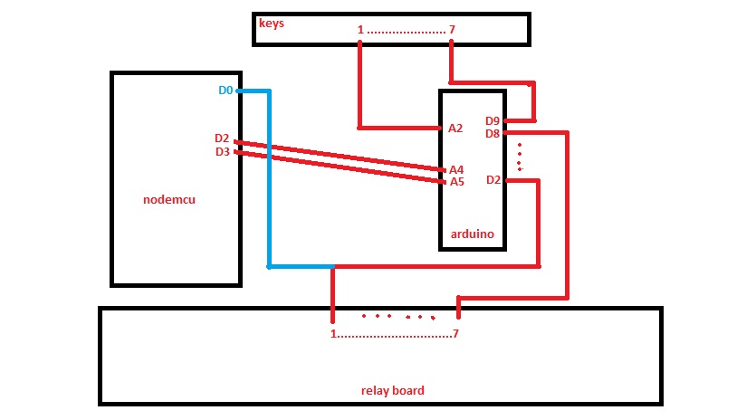
LKKKKK.jpg (44.22 KiB) Viewed 15669 times
((sorry in this photo have a problem. i use D1 and D2 for I2C.))
in this photo i connect output arduino(relay ) to input nodemcu. with this work send to domoticz is ok(i create a input switch in espeasy . BUT there is one problem . i told before. when i turn on and turn off a key fast . or with domoticz turn on and off a light fast, so there will be a loop and relay run on/off again and again... for (for example ) 30 times.on/off/on/off/on...
i can not found why there is this problem. i dont want use other modules . i want fix this issue. because there is a software problem about this that we can solve.i am not a strong programmer. . .

reza
Normal user
Posts: 88
Joined: 13 Jun 2017, 21:14

Re: help to use a PME for input switch

#31 Post by reza » 19 Jun 2017, 12:04

i think if a friend help me to add a line in my sketch , so we can send state of relay to controller directlly By espeasy Interface.
for example:

Code: Select all

  stateA = digitalRead(relayPinA);
  debouncerA.update();
  int valueA = debouncerA.read();
  if (valueA != oldValueA) {
    digitalWrite(relayPinA, !stateA);
    ********with a command we can send "!stateA" value to controller ********
    oldValueA = valueA;
  }

Post Reply

Who is online

Users browsing this forum: No registered users and 71 guests