I have been looking for several days and I am going in circles.
So I appeal to specialists for help.
I first created a mysensors (https://www.mysensors.org/build/pulse_water) avec arduino nano+NRF24L01 and a YF-B1 pulse counter with the following characteristics:
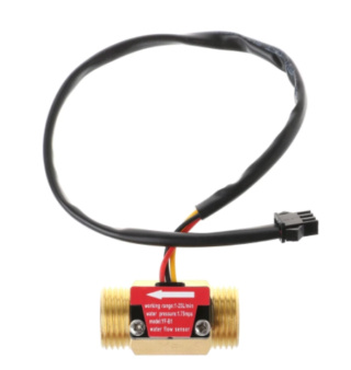
Mini. Working Voltage : DC 4.5V
Max. Working Current : 15mA (DC 5V)
Working Voltage : DC 5V~15V
Flow Rate Range : 1~25L/min
Frequency : F=11*Q(Q=L/MIN)
Load Capacity : ≤10mA (DC 5V)
Water Pressure : ≤1.75MPa
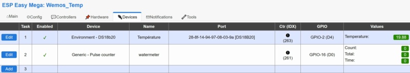
Not being satisfied with the result and wanting to favor the use of wifi over radio, I changed my mind to espeasy with a wemos d1 mini.
I made a first connection which gave nothing:
Red on 5V from wemos
Yellow on D4 of the wemos
Black on Wemos Ground
However I read too late that the GPIO of the wemos does not support 5V.
So I looked for the possible solutions and came across the voltage divider bridge. (Very obscure to me)
So I redid an assembly like this: (imagine the 3 wires at the top connected to the pulse meter.
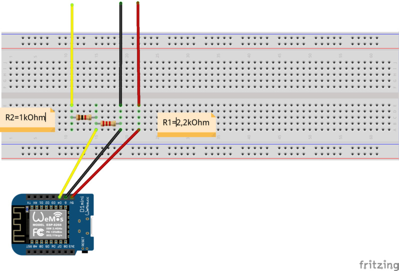
Is this assembly correct?
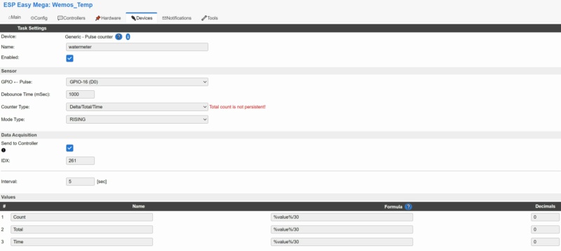
No data is displayed in espeasy.
Thank you in advance for your collaboration with this noob that I am.