Page 1 of 1
Wemos D1 with pulse counter on domoticz
Posted: 29 Dec 2020, 11:23
by Matthias
Hello,
I have been looking for several days and I am going in circles.
So I appeal to specialists for help.
I first created a mysensors (
https://www.mysensors.org/build/pulse_water) avec arduino nano+NRF24L01 and a YF-B1 pulse counter with the following characteristics:
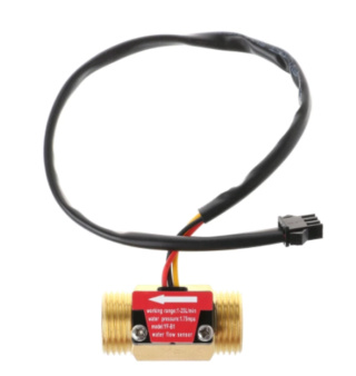
Mini. Working Voltage : DC 4.5V
Max. Working Current : 15mA (DC 5V)
Working Voltage : DC 5V~15V
Flow Rate Range : 1~25L/min
Frequency : F=11*Q(Q=L/MIN)
Load Capacity : ≤10mA (DC 5V)
Water Pressure : ≤1.75MPa
Not being satisfied with the result and wanting to favor the use of wifi over radio, I changed my mind to espeasy with a wemos d1 mini.
I made a first connection which gave nothing:
Red on 5V from wemos
Yellow on D4 of the wemos
Black on Wemos Ground
However I read too late that the GPIO of the wemos does not support 5V.
So I looked for the possible solutions and came across the voltage divider bridge. (Very obscure to me)
So I redid an assembly like this: (imagine the 3 wires at the top connected to the pulse meter.
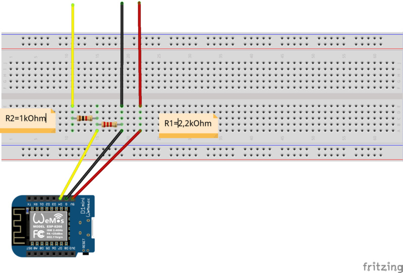
Is this assembly correct?
No data is displayed in espeasy.
Thank you in advance for your collaboration with this noob that I am.
Re: Wemos D1 with pulse counter on domoticz
Posted: 29 Dec 2020, 11:38
by Ath
Well, if you have exposed that GPIO to 5V then there is a chance that it is now fried, so you'd better use another GPIO for further experiments. You can test that GPIO by setting it up as a Switch device and connecting the port to 3.3V or gnd and look at the result in the Devices page (set the Interval at a few seconds to have the value automatically updated, or click the Devices tab to update the page). If that doesn't change State in a 1 or 0 you can safely assume the GPIO has died.
A few remarks though:
- What version of ESPEasy are you using? Most recent builds can be found here:
https://github.com/letscontrolit/ESPEasy/releases
- Pulse counters must be configured as Device/Task 1..4, that is a current limitation of ESPEasy (when trying to set one up on higher numbered tasks, ESPEasy should give a warning on the Device page on recent builds)
Re: Wemos D1 with pulse counter on domoticz
Posted: 29 Dec 2020, 11:47
by Matthias
In order to verify the gpio i test it with a DS18b20 and it works.
So i think the gpio was not damaged.
I use this version of espeasy : ESP_Easy_mega_20201227_normal_ESP8266_4M1M
Pulse counters must be configured as Device/Task 1..4, that is a current limitation of ESPEasy (when trying to set one up on higher numbered tasks, ESPEasy should give a warning on the Device page on recent builds)
I don't understand this. Could you explain me in details ?
Re: Wemos D1 with pulse counter on domoticz
Posted: 29 Dec 2020, 11:50
by Matthias
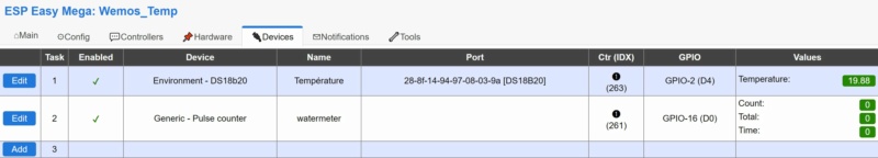
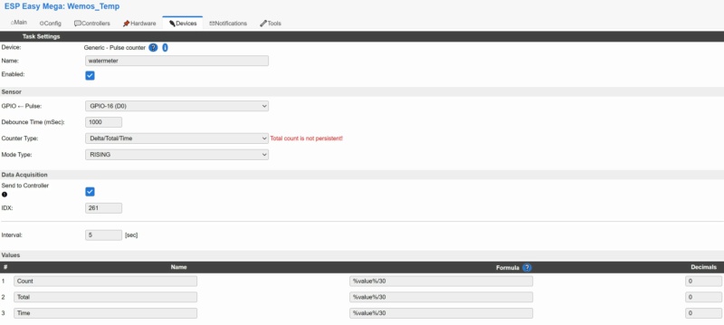
My espeasy configuration :
Re: Wemos D1 with pulse counter on domoticz
Posted: 29 Dec 2020, 11:59
by Ath
That all looks just fine to me, with the pulse-counter on Task 2 that is in range with 1..4

(I don't own pulse-counters so I can't replay, but pulse counters in general are known to work)
Do you have access to an oscilloscope, or similar measuring device, to confirm the working of the pulse-counter? (A multimeter could give a reading > 0 when there is flow through the device, and 0 when there is no flow)
Re: Wemos D1 with pulse counter on domoticz
Posted: 29 Dec 2020, 15:55
by TD-er
Does this sensor need a pull-up resistor to work?
If so then you may not even need the other resistors as voltage divider as you could then connect the "signal" line via a resistor to 3v3 of the ESP.
So please have a look at the documentation of that sensor.
By the way, when searching for the sensor I came across our own documentation
 https://espeasy.readthedocs.io/en/lates ... FS401.html
Edit2:
Hmm I found this one on AliExpress:
https://www.aliexpress.com/i/32790011212.html
But the wiring description makes me wonder if you may have connected it as it should be connected.
(12) wire connection :
Terminal 1 ( Red) : Vdd " + "
Terminal 2 (Black) Vout " - "
Terminal 3 ( Yellow ) Gnd : output
Not stating you should immediately try a different connection, but rather double/triple check what pin needs to be connected to what.
The description is rather confusing, with Red/Black be either +/- (as it should) and also stating black is output and yellow is GND. (which is outright stupid if it is done like that)
Re: Wemos D1 with pulse counter on domoticz
Posted: 29 Dec 2020, 16:28
by Matthias
Hi,
Very interesting your first link.
I think that the yellow wire is a signal 5V.
What is the principe of pull-up, i don't know.
I try with "change" parameter in espeasy.
It works with mysensors and arduino nano.
Re: Wemos D1 with pulse counter on domoticz
Posted: 29 Dec 2020, 16:41
by Ath
On the ESPEasy documentation page it states that GPIO-16 (D0) is not compatible with pulse counters, and you connected it to... GPIO-16 (D0), according to above screenshot. Probably better select another GPIO?

- Screenshot - 29_12_2020 , 17_05_14.png (2.77 KiB) Viewed 9201 times
Re: Wemos D1 with pulse counter on domoticz
Posted: 29 Dec 2020, 20:51
by Matthias
I do the test with D5 and the same parameter of your link and it doesn't work.
Do I take a risk to try an assembly with a pull up resistance?
Re: Wemos D1 with pulse counter on domoticz
Posted: 29 Dec 2020, 22:20
by TD-er
Do you have the schematic of how it was working with the other setup?
The principle of a pull-up resistor is quite simple.
It is a resistor connected between the higher voltage and the signal line (often a GPIO pin)
So what this does is, it "pulls" the level high by default.
On the sensor side, you can then simply "pull" the line to GND via a transistor (or a switch).
This makes it simple to connect a sensor to just about any micro controller as the pull-up determines the level of the "high" signal, which makes it compatible with just about any voltage level (1.8V, 3.3V, 5V, etc)
But the sensor must be able to handle it of course, to have a signal level on the data pin which may be higher then its own voltage pin when the unit is initially powered for example.
Re: Wemos D1 with pulse counter on domoticz
Posted: 29 Dec 2020, 22:53
by Matthias
Thank you for infomation.
I check withmy arduino and mysensors (
https://www.mysensors.org/build/pulse_water). This is the system that worked yesterday but today it doesn't work.
I think that the watermeter is broken.
Re: Wemos D1 with pulse counter on domoticz
Posted: 29 Dec 2020, 23:38
by TD-er
From your own link:
Code: Select all
void setup()
{
    // initialize our digital pins internal pullup resistor so one pulse switches from high to low (less distortion)
    pinMode(DIGITAL_INPUT_SENSOR, INPUT_PULLUP);
So it does set the internal pull-up on that pin.
I noticed we don't have the pull-up option on the pulse counter plugin, so I guess you should add one yourself.... that is, if you used that code before.
Re: Wemos D1 with pulse counter on domoticz
Posted: 29 Dec 2020, 23:43
by Matthias
Can you tell me the assembly that I must follow precisely please?
I am lost with this new notion.
Re: Wemos D1 with pulse counter on domoticz
Posted: 29 Dec 2020, 23:48
by TD-er
Just use some resistor like 10k (value isn't that important) between the signal pin and 3v3.
But make sure to measure the voltage on the signal line and GND of the sensor before connecting it to the ESP, to see what its voltage is.
And also check if you can make it change value by turning the wheel in the sensor slowly.