PCB Idea's...

Moderators: grovkillen, Stuntteam, TD-er

Message
Author
Remco
Normal user
Posts: 63
Joined: 15 Apr 2015, 16:07

PCB Idea's...

#1 Post by Remco » 20 Dec 2015, 15:45

Hi,

We are going to add some hardware to this forum, and we need some idea of what's needed.

The first is a PCB for a NodeMcu with some standard connection options for a Dallas sensors i2C devices and maybe a mosfet for switching more powerful devices.

Second would be a small case with a possibility to mount also a oled display.

Third a PCB that fits in the standard wall mount's for easy tucking a ESP away. :)

So if you have suggestion’s for these or other hardware idea's, shoot away!

:mrgreen:

Backbone
Normal user
Posts: 106
Joined: 06 Oct 2015, 22:12

Re: PCB Idea's...

#2 Post by Backbone » 20 Dec 2015, 18:33


kr0815
Normal user
Posts: 136
Joined: 18 Nov 2015, 18:24

Re: PCB Idea's...

#3 Post by kr0815 » 20 Dec 2015, 19:03

Good Idea with the PCB

For those that don´t want to wait:

http://www.ebay.de/itm/like/26193468643 ... s&lpid=106

forget the batterie holder, and you have to remove / cut the LEDs (small ones, not the RGB) if you want to attach sensors to the pin, but preatty easy to do

ordered several, delivery was always 10 - 14 days

Remco
Normal user
Posts: 63
Joined: 15 Apr 2015, 16:07

Re: PCB Idea's...

#4 Post by Remco » 21 Dec 2015, 15:53

We are looking for more dedicated solution's that we want to design and build... But is is a start.

When we have some design idea's we will share them here. :D

mkotek
Normal user
Posts: 116
Joined: 15 Dec 2015, 10:58
Location: Lomianki, Poland
Contact:

Re: PCB Idea's...

#5 Post by mkotek » 21 Dec 2015, 17:12

I am all in for a small board that would use ESP-12E and fit into standard wall mount. For the power, I would recommend the HLK-PM01 http://www.aliexpress.com/item/5-pcs-HL ... 02093.html.

With that, I have a question, if anyone used this item for power conversion:
http://www.aliexpress.com/item/220V-to- ... 37836.html?
Michal 'Kotek', greetings from Poland. Zapraszam na mój blog o automatyce domowej po polsku: http://www.ukotka.com.

MiKa1975
Normal user
Posts: 17
Joined: 03 Dec 2015, 13:37

Re: PCB Idea's...

#6 Post by MiKa1975 » 21 Dec 2015, 18:03


mkotek
Normal user
Posts: 116
Joined: 15 Dec 2015, 10:58
Location: Lomianki, Poland
Contact:

Re: PCB Idea's...

#7 Post by mkotek » 21 Dec 2015, 18:17

MiKa1975 wrote:I prefer this one ;)
http://sk.farnell.com/vigortronix/vtx-2 ... dp/2401030
MiKa
Is there any particular reason? The price is 2,5x higher and HLK has been tested by a guy in Danmark who tests USB chargers and was deemed quite ok. Of course this is not well known brand, but the cost difference is quite high, if you are thinking about mass usage. I am open to your rationale however (esp. related to safety).
Michal 'Kotek', greetings from Poland. Zapraszam na mój blog o automatyce domowej po polsku: http://www.ukotka.com.

User avatar
costo
Normal user
Posts: 500
Joined: 21 Nov 2015, 15:03
Location: NL, zw-NB

Re: PCB Idea's...

#8 Post by costo » 21 Dec 2015, 18:26

My idea is to have a sort of subsystem near my frontdoor. Some inputs and some outputs. 1 or 2 relais to switch the frontdoor-light/dooropener. Powersupply for the ESP and fuse(s)+relais for the high voltage lights. All the power connections with screw-terminals. Powersupply either a small 230/5V pcb module or place for a 230V/USB supply.

Some inputs for the doorbell and other switches and sensors.
Output for the relais to steer the frontdoor light and outputs for a few leds.

I guess it could be made with place for either a ESP01 , the ESP07/08/12 adapterboard , the ESP201 or probably a NodeMCU. The footprint on the PCB would be just a little bigger than the largest module.

So it would be a fairly large board that would need to be put inside a project box for safety.

Ger
Normal user
Posts: 71
Joined: 05 Sep 2015, 18:09

Re: PCB Idea's...

#9 Post by Ger » 21 Dec 2015, 23:07


Remco
Normal user
Posts: 63
Joined: 15 Apr 2015, 16:07

Re: PCB Idea's...

#10 Post by Remco » 22 Dec 2015, 00:14

Some great input!

And for the modules we want to use the ESP12F, it has some good improvements regarding the the antenna.

Regarding the power modules, we are looking at some different version's. Safety is of course also an point to look at with 230V. ;)

Does anybody here have some experience with LCD touchscreens in combination with the ESP?

Martinus

Re: PCB Idea's...

#11 Post by Martinus » 22 Dec 2015, 09:01

Well one of my favorite boards from the old Nodo project is still this one:
Image
It's based on ATMega328P, has protected analog inputs, ULN2003 driven outputs, IR LED, IR receiver, Buzzer, RTC.
Maybe there's still a need for a board like this. Replace the ATMega328P with NodeMCU 1.0 board headers and it could be a new start.

About a nice housing, I tried to mount an LCD display using the Stanley knife, but it's not an impressive result. This is my good old Alarm unit(the above displayed board sits inside)
Image

Still using prototype boards here. Room for improvement?
Image

But to be honest, most of my units are still running the old ATMega328 using the ESP Easy as a WiFi bridge.
Image
I'm still in favour of having those 3.5" jack connectors to connect external sensors, although the default stereo types are not suitable for I2C sensors (would need 4 wires). But easy to connect the wired Dallas sensors, LDR's and pulscounter sensors.

This box could also need an update. It's a 3 channel pulse counter for electricity, gas and water.
Image

DMeekelenkamp
Normal user
Posts: 35
Joined: 11 Nov 2015, 13:52

Re: PCB Idea's...

#12 Post by DMeekelenkamp » 22 Dec 2015, 10:23

I also still use the nodo. i love the simplicity of the espeasy, but the nodo is so stable and versatile i wish it could run with a controller like domoticz and sensors from espeasy. But i never heard heard a thing from Paul do you still have contact with him Martinus?

Martinus

Re: PCB Idea's...

#13 Post by Martinus » 22 Dec 2015, 14:16

I'm only using the Nodo Small in combination with ESP Easy and Domoticz. Just because the low level sensor part was already running stable for many years and it only needed a way to communicate to Domoticz. The upgraded Nodo unit's are running stable now for several months and now I'm just to lazy to change them to native ESP sensors.

I've left the Nodo team back in april and I have no contact with Paul anymore. But Remco and John from the Nodo team have joined the ESP community here. So we could expect some hardware stuff coming...

buitermark
Normal user
Posts: 10
Joined: 28 Oct 2015, 16:41
Location: Rhenen

Re: PCB Idea's...

#14 Post by buitermark » 22 Dec 2015, 15:13

Why not a small ESP8266 Multi sensor device ?

Like Aetec has for the Z-wave community

But basically not working with seperate add-on boards, that would make it 'big', but the dedicated smd-chips.

Some whishes...

- Battery/lipo/18650 powered
- Temperature (DS18b20)
- Humidity (SI7021)
- barometic pressure (bmp085)
- Lightintensity (BH1750/TSL2561)

And maybe
- PIR Motion detection
- BT (tag-detection whom/where ?)
- i/o for doorsensor open/close or some kind of switch

tim
Normal user
Posts: 52
Joined: 05 Dec 2015, 11:24

Re: PCB Idea's...

#15 Post by tim » 22 Dec 2015, 15:38

buitermark wrote:Some whishes...
- Battery/lipo/18650 powered
But how long will it run on the battery? I think ESP is very power hungry. Maybe you need MySensors for running on battery.

buitermark
Normal user
Posts: 10
Joined: 28 Oct 2015, 16:41
Location: Rhenen

Re: PCB Idea's...

#16 Post by buitermark » 22 Dec 2015, 20:54

But how long will it run on the battery? I think ESP is very power hungry. Maybe you need MySensors for running on battery.
I don't know, but I think i've heard/read that the ESP can run very long in Deep Sleep mode ?

Just to compare...
Aeonlabs claims for the sensor 2 years on a pair of CR123A batteries..

BertB
Normal user
Posts: 1049
Joined: 25 Apr 2015, 14:39

Re: PCB Idea's...

#17 Post by BertB » 23 Dec 2015, 13:20

buitermark wrote:
But how long will it run on the battery? I think ESP is very power hungry. Maybe you need MySensors for running on battery.
I don't know, but I think i've heard/read that the ESP can run very long in Deep Sleep mode ?

Just to compare...
Aeonlabs claims for the sensor 2 years on a pair of CR123A batteries..
Which device is that?

tim
Normal user
Posts: 52
Joined: 05 Dec 2015, 11:24

Re: PCB Idea's...

#18 Post by tim » 23 Dec 2015, 16:48

DMeekelenkamp wrote:I also still use the nodo. i love the simplicity of the espeasy, but the nodo is so stable and versatile i wish it could run with a controller like domoticz and sensors from espeasy. But i never heard heard a thing from Paul do you still have contact with him Martinus?
I stopped with Nodo, use the Nodo Shield for RFLink now thanks to Stuntteam (!) and have MySensors running on some Mini Pro units that used to be Nodo Small. And starting to use more ESP Easy.

I just checked Nodo forum and is terribly silent there. Maybe whole team has left.

buitermark
Normal user
Posts: 10
Joined: 28 Oct 2015, 16:41
Location: Rhenen

Re: PCB Idea's...

#19 Post by buitermark » 23 Dec 2015, 20:30

BertB wrote:
buitermark wrote:
But how long will it run on the battery? I think ESP is very power hungry. Maybe you need MySensors for running on battery.
I don't know, but I think i've heard/read that the ESP can run very long in Deep Sleep mode ?

Just to compare...
Aeonlabs claims for the sensor 2 years on a pair of CR123A batteries..
Which device is that?
It's the aeon labs multisensor 6 more info here http://aeotec.com/z-wave-sensor
Just read the page, to find " 4x times the life.
Forget changing your batteries a few times a year. MultiSensor 6 now works up to 2 years before you need to change batteries offering 4 times the battery life of the first MultiSensor."

Very nice product, but Z-Wave.

ESP-Easy - Zwave interface ?

maluko
Normal user
Posts: 112
Joined: 02 Sep 2015, 00:49

Re: PCB Idea's...

#20 Post by maluko » 23 Dec 2015, 21:42

this was my first pcb that i did,

http://www.esp8266.nu/forum/viewtopic.php?f=2&t=269

next step is to do with esp07/12.

BertB
Normal user
Posts: 1049
Joined: 25 Apr 2015, 14:39

Re: PCB Idea's...

#21 Post by BertB » 24 Dec 2015, 13:39

buitermark wrote: It's the aeon labs multisensor 6 more info here http://aeotec.com/z-wave-sensor
Just read the page, to find " 4x times the life.
Forget changing your batteries a few times a year. MultiSensor 6 now works up to 2 years before you need to change batteries offering 4 times the battery life of the first MultiSensor."

Very nice product, but Z-Wave.

ESP-Easy - Zwave interface ?
I have the previous version and it needs a refill 2-3 times per year.

buitermark
Normal user
Posts: 10
Joined: 28 Oct 2015, 16:41
Location: Rhenen

Re: PCB Idea's...

#22 Post by buitermark » 24 Dec 2015, 14:51

BertB wrote: I have the previous version and it needs a refill 2-3 times per year.
That's one of the reasons why they have completely redesigned the older version, and now claim

4 times the life.
Forget changing your batteries a few times a year.
MultiSensor 6 now works up to 2 years before you need to change batteries offering 4 times the battery life of the first MultiSensor.'


So basicly, you're telling us, what they claim could be true !?

Remco
Normal user
Posts: 63
Joined: 15 Apr 2015, 16:07

Re: PCB Idea's...

#23 Post by Remco » 25 Dec 2015, 00:57

maluko wrote:this was my first pcb that i did,

http://www.esp8266.nu/forum/viewtopic.php?f=2&t=269

next step is to do with esp07/12.
Looks great!

We have some idea to work with now.

The Openthermgateway PCB that we designed with an Arduino and NRF is going to be changed to a NodeMCU. Works great, only the ser2lan software was a bit difficult to get working with the PIC on the opentherm gateway. We now use the ESP-Link firmware from jeelabs.

Lars65
New user
Posts: 4
Joined: 02 Oct 2015, 07:03

Re: PCB Idea's...

#24 Post by Lars65 » 26 Dec 2015, 17:55

Hi!

Anyone who has a schematic of a simple dev board for the ESP 12E?
I mill my own PCB:s on my homebuilt milling machine, but I do really suck at electronics. :)

rtenklooster
Normal user
Posts: 320
Joined: 15 Apr 2015, 14:17

Re: PCB Idea's...

#25 Post by rtenklooster » 30 Dec 2015, 19:13

Ger wrote:I have ordered the following:
http://www.aliexpress.com/item/ESP8266- ... 99462.html
Does dis product contains both parts displayed on the first picture?
So the usb - serial board + the esp module already soldered on the top pcb?

If so it pretty cheap!
Richard - Groningen (NL) - Image

BertB
Normal user
Posts: 1049
Joined: 25 Apr 2015, 14:39

Re: PCB Idea's...

#26 Post by BertB » 30 Dec 2015, 20:45

Lars65 wrote:Hi!

Anyone who has a schematic of a simple dev board for the ESP 12E?
I mill my own PCB:s on my homebuilt milling machine, but I do really suck at electronics. :)
I'd say, Google for NodeMCU V1.0.

Ger
Normal user
Posts: 71
Joined: 05 Sep 2015, 18:09

Re: PCB Idea's...

#27 Post by Ger » 07 Jan 2016, 15:30

I am waiting on the ESP8266 Witty boards I ordered at AliExpress http://www.aliexpress.com/item/ESP8266- ... 99462.html
As far as I can see it is a ESP8266 board with USB power supply connected to a baseboard with USB serial converter to program the board.
For the sensors I am going to use a prototype PCB board to connect the sensors to and will mount to connectors on it to put the ESP board on to it.
In this way I can mount the prototype board where I want it, but when I have to program the ESP I don't have to disconnect the sensors.
I just have to pullout the ESP board. ;)

mkotek
Normal user
Posts: 116
Joined: 15 Dec 2015, 10:58
Location: Lomianki, Poland
Contact:

Re: PCB Idea's...

#28 Post by mkotek » 07 Jan 2016, 15:34

Ger wrote:I am waiting on the ESP8266 Witty boards I ordered at AliExpress http://www.aliexpress.com/item/ESP8266- ... 99462.html
As far as I can see it is a ESP8266 board with USB power supply connected to a baseboard with USB serial converter to program the board.
For the sensors I am going to use a prototype PCB board to connect the sensors to and will mount to connectors on it to put the ESP board on to it.
In this way I can mount the prototype board where I want it, but when I have to program the ESP I don't have to disconnect the sensors.
I just have to pullout the ESP board. ;)
This is exactly what I thought. I am making my sensors on the basis of goldpin headers so I can pull ESP-12 and ESP-01 from it and reprogram it at the desk and plug it back. Let us know, when the board arrives - I am not clear if you are able to use bottom part without top for programming only.
Michal 'Kotek', greetings from Poland. Zapraszam na mój blog o automatyce domowej po polsku: http://www.ukotka.com.

asm7100
Normal user
Posts: 96
Joined: 13 Sep 2015, 21:45
Location: Denmark

Re: PCB Idea's...

#29 Post by asm7100 » 07 Jan 2016, 21:34

I have made this one for esp01.
esptcp22com_pcb.png
esptcp22com_pcb.png (8.28 KiB) Viewed 28414 times
5xESP-01 - 3xESP-12 - 2xESP-12E 3xRPIb+ - 1xBPIm1 - 3xACTi DOME - 7xACTi Indoor cam. Lot off cisco equ.

asm7100
Normal user
Posts: 96
Joined: 13 Sep 2015, 21:45
Location: Denmark

Re: PCB Idea's...

#30 Post by asm7100 » 07 Jan 2016, 21:36

And the diagram.
esptcp22com_sch.png
esptcp22com_sch.png (21 KiB) Viewed 28414 times
I have had made 10 pices of this and thay works
5xESP-01 - 3xESP-12 - 2xESP-12E 3xRPIb+ - 1xBPIm1 - 3xACTi DOME - 7xACTi Indoor cam. Lot off cisco equ.

rtenklooster
Normal user
Posts: 320
Joined: 15 Apr 2015, 14:17

Re: PCB Idea's...

#31 Post by rtenklooster » 09 Jan 2016, 13:10

Image
These boards are so dirt cheap i wouln't reconsider other ones.
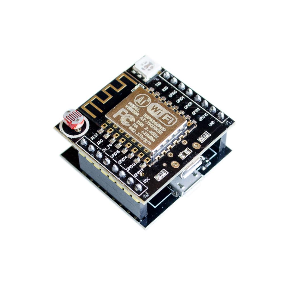
Equipped with esp-12f module, a rgb led, a micro usb to serial converter it's smaller then a node mcu for just 2,50 euro i can recommand it to everyone..

The programmer with reset and program switch can be taken off, the top pcb has also a micro usb for powering, a 3.3v converter and a reset switch
Richard - Groningen (NL) - Image

Ger
Normal user
Posts: 71
Joined: 05 Sep 2015, 18:09

Re: PCB Idea's...

#32 Post by Ger » 09 Jan 2016, 22:32

I just received one and flashed it with EspEasy as nodemcu without any problem.
I don't know if the RGB led and LDR can be a problem if you are using these pins for other usage.
What I can see it is not a real problem to disconnect them by cutting the LDR and the resistors of the RGB LED.
I think I have the source code and other documentation of the original firmware.
The documentation is in a chinese word document.
I will try to figure out to which pins the LDR and RGB led are connected.
The pinout is not breadboard friendly, but it is usable if you use two breadboards next to each other.
As described by rtenklooster you can use the bottom board to program the top board with the esp12f.
You can use the top board on its own with a micro usb power supply.
I am very happy with it :D

Ger
Normal user
Posts: 71
Joined: 05 Sep 2015, 18:09

Re: PCB Idea's...

#33 Post by Ger » 10 Jan 2016, 00:02

The VCC pin is 5V, not 3.3V, this is a pitty :(
the cause of it is that there is only a voltage regulator on the top esp12f board, the bottom board is just USB interface.
So I have to think about a trick to get the 3v3 on a own bottom sensor board, or put also a regulator on a own bottom sensor board.
According to me it is possible to solder a wire to the 3v3.
The LDR is as expected connected to the ADC.
The RGB led is on GPIO12(Green) GPIO13(Blue) GPIO15(Red)

rtenklooster
Normal user
Posts: 320
Joined: 15 Apr 2015, 14:17

Re: PCB Idea's...

#34 Post by rtenklooster » 10 Jan 2016, 00:04

Ger wrote: I will try to figure out to which pins the LDR and RGB led are connected.
I am very happy with it :D
RGB are GPIO 11 12 13
LDR = ADC
The led might be a problem when using the pins as a input, but it's easy to cut off.
I don't use breadboards, just solder some headers on a prototype pcb.
I share the joy :) one of the nicest boards i've seen so far, compact, way cheaper then a esp12f + a PCB, even because you get a usb converter / programmer for free!
Richard - Groningen (NL) - Image

mkotek
Normal user
Posts: 116
Joined: 15 Dec 2015, 10:58
Location: Lomianki, Poland
Contact:

Re: PCB Idea's...

#35 Post by mkotek » 10 Jan 2016, 07:34

And what about lower signal sensitivity caused by USB port on the top board reported initially?
Michal 'Kotek', greetings from Poland. Zapraszam na mój blog o automatyce domowej po polsku: http://www.ukotka.com.

User avatar
costo
Normal user
Posts: 500
Joined: 21 Nov 2015, 15:03
Location: NL, zw-NB

Re: PCB Idea's...

#36 Post by costo » 10 Jan 2016, 11:18

mkotek wrote:And what about lower signal sensitivity caused by USB port on the top board reported initially?
It is not the USB that is near the PCB antenna, it is a button that is right under it ,reset button I think, and some traces to led and/or ldr that may block the WiFi signal partly.
I like to see a comparison of WiFi receiving signal strength of this board and other boards .

mkotek
Normal user
Posts: 116
Joined: 15 Dec 2015, 10:58
Location: Lomianki, Poland
Contact:

Re: PCB Idea's...

#37 Post by mkotek » 10 Jan 2016, 11:26

Well, if it is a button, one can most likely desolder it if this causes the signal issue then. But definitely, the comparison for signal strenght would be helpful.
Michal 'Kotek', greetings from Poland. Zapraszam na mój blog o automatyce domowej po polsku: http://www.ukotka.com.

Ger
Normal user
Posts: 71
Joined: 05 Sep 2015, 18:09

Re: PCB Idea's...

#38 Post by Ger » 10 Jan 2016, 16:23

I think the signal maybe is affected by the button but what I know of HF is that it is very complicated stuff.
At the moment I have the unit on the bottom floor with the antenna facing up and it is connected to a access point on the second floor with two concrete floors between.
It stays connected when I turn the unit upside down.

User avatar
costo
Normal user
Posts: 500
Joined: 21 Nov 2015, 15:03
Location: NL, zw-NB

Re: PCB Idea's...

#39 Post by costo » 10 Jan 2016, 22:59

Ger wrote:I think the signal maybe is affected by the button but what I know of HF is that it is very complicated stuff.
At the moment I have the unit on the bottom floor with the antenna facing up and it is connected to a access point on the second floor with two concrete floors between.
It stays connected when I turn the unit upside down.
Sure, HF is usually complicated stuff. Calculating field strength in space without real objects is simple because you have a homogeneous EM-Field. in the real world you have a inhomogeneous EM-field which makes it very complicated.
This video illustrates that https://www.youtube.com/watch?v=aqqEYz38ens it shows field strength mapping in part of a room taken with an ESP8266 and displays it in 3D on a PC.

If (I say IF) the antenna of the ESP8266-12E/F module on the Mini-NodeMCU is optimized then every metallic object close to the antenna (< 15mm or <1/8 wavelength) will negatively influence the behaviour of the PCB antenna. If you want to do some comparisons between several ESP boards you should do several measurements on slightly different locations and avarage the result for each board.

maluko
Normal user
Posts: 112
Joined: 02 Sep 2015, 00:49

Re: PCB Idea's...

#40 Post by maluko » 12 Jan 2016, 23:33

i have put the new project that i build on this post because it´s the follow of first, so take a look here

Thanks

BertB
Normal user
Posts: 1049
Joined: 25 Apr 2015, 14:39

Re: PCB Idea's...

#41 Post by BertB » 27 Jan 2016, 17:23

costo wrote:
mkotek wrote:And what about lower signal sensitivity caused by USB port on the top board reported initially?
It is not the USB that is near the PCB antenna, it is a button that is right under it ,reset button I think, and some traces to led and/or ldr that may block the WiFi signal partly.
I like to see a comparison of WiFi receiving signal strength of this board and other boards .
@costo,
Today I received a number of these bords and I must say, I am a bit disappointed by the sensitivity of the antenna. When I do a wifiscan through serial interface, I read -80 db, but I cannot get in touch with the router.
Another, ordinary, ESP-12 or 12E in the vicinity reads -78 and has no problem at all.

I took one of these boards closer to the router and now connectivity is flawless.

Where did you find remarks about the switch? (which is connected to GPIO4.)
Just removed the switch, didn't help much.

BertB
Normal user
Posts: 1049
Joined: 25 Apr 2015, 14:39

Re: PCB Idea's...

#42 Post by BertB » 27 Jan 2016, 17:33

BertB wrote:
costo wrote:
mkotek wrote:And what about lower signal sensitivity caused by USB port on the top board reported initially?
It is not the USB that is near the PCB antenna, it is a button that is right under it ,reset button I think, and some traces to led and/or ldr that may block the WiFi signal partly.
I like to see a comparison of WiFi receiving signal strength of this board and other boards .
@costo,
Today I received a number of these bords and I must say, I am a bit disappointed by the sensitivity of the antenna. When I do a wifiscan through serial interface, I read -80 db, but I cannot get in touch with the router.
Another, ordinary, ESP-12 or 12E in the vicinity reads -78 and has no problem at all.

I took one of these boards closer to the router and now connectivity is flawless.

Where did you find remarks about the switch? (which is connected to GPIO4.)
Just removed the switch, didn't help much.
@rtenklooster what are your experiences so far?

Ger
Normal user
Posts: 71
Joined: 05 Sep 2015, 18:09

Re: PCB Idea's...

#43 Post by Ger » 27 Jan 2016, 20:27

I am using the modules without problems.
I use a prototype PCB with headers on it and a 3.3v power supply module
http://www.aliexpress.com/item/Free-shi ... 63198.html

rtenklooster
Normal user
Posts: 320
Joined: 15 Apr 2015, 14:17

Re: PCB Idea's...

#44 Post by rtenklooster » 27 Jan 2016, 23:03

BertB wrote:
BertB wrote:
@rtenklooster what are your experiences so far?
It's working flawlessly. But i must say o have an excellent wifi network coverage trough my whole house.
wifi signal has never been an issue for me, just buy a good wifi router, like the netgear nighthawk.
Richard - Groningen (NL) - Image

User avatar
costo
Normal user
Posts: 500
Joined: 21 Nov 2015, 15:03
Location: NL, zw-NB

Re: PCB Idea's...

#45 Post by costo » 28 Jan 2016, 20:47

BertB wrote: @costo,
Today I received a number of these bords and I must say, I am a bit disappointed by the sensitivity of the antenna. When I do a wifiscan through serial interface, I read -80 db, but I cannot get in touch with the router.
Another, ordinary, ESP-12 or 12E in the vicinity reads -78 and has no problem at all.

I took one of these boards closer to the router and now connectivity is flawless.

Where did you find remarks about the switch? (which is connected to GPIO4.)
Just removed the switch, didn't help much.
I am waiting for my Mini NodeMCU board to arrive and do some testing.
If the difference between this and the normal NodeMCU is about -2dB it will usually be no problem. Unless you are far away from your router .
The switch right under the antenna, it was a guess that it was a reset button, I do/did not know to which pin it is connected.

BertB
Normal user
Posts: 1049
Joined: 25 Apr 2015, 14:39

Re: PCB Idea's...

#46 Post by BertB » 28 Jan 2016, 23:07

costo wrote: I am waiting for my Mini NodeMCU board to arrive and do some testing.
If the difference between this and the normal NodeMCU is about -2dB it will usually be no problem. Unless you are far away from your router .

The switch right under the antenna, it was a guess that it was a reset button, I do/did not know to which pin it is connected.
Exactly my point. -2dB should not be the problem here, but communication works two ways, I do not know the strength of the signal transmitted bij the ESP. If that is not strong enough to reach the router, it could cause problems too.

Lars65
New user
Posts: 4
Joined: 02 Oct 2015, 07:03

Re: PCB Idea's...

#47 Post by Lars65 » 13 Feb 2016, 08:26

This is a good initiative from mysensors: https://www.openhardware.io/
Could maybe also be something for ESP8266 also?

tozett
Normal user
Posts: 734
Joined: 22 Dec 2015, 15:46
Location: Germany

Re: PCB Idea's...

#48 Post by tozett » 03 Mar 2016, 08:30

if anybody skillfull ever comes here while considering to build a PCB for solar-powered/batterie-running ESP
(as garden sensor?), i found this one. maybe as a blueprint?

TPS78233 3.3V 150mA Regulator
MCP73832 LiPo Battery Charger
MAX17048 LiPo Battery Fuel Gauge

-> https://www.kickstarter.com/projects/qt ... escription

BertB
Normal user
Posts: 1049
Joined: 25 Apr 2015, 14:39

Re: PCB Idea's...

#49 Post by BertB » 03 Mar 2016, 13:10

tozett wrote:if anybody skillfull ever comes here while considering to build a PCB for solar-powered/batterie-running ESP
(as garden sensor?), i found this one. maybe as a blueprint?

TPS78233 3.3V 150mA Regulator
MCP73832 LiPo Battery Charger
MAX17048 LiPo Battery Fuel Gauge

-> https://www.kickstarter.com/projects/qt ... escription
Somewhere in this forum, someone tried this before.
ESP can only run on a solar charged battery, when it is allowed to enter sleep mode and that brings some new problems with it.

tozett
Normal user
Posts: 734
Joined: 22 Dec 2015, 15:46
Location: Germany

Re: PCB Idea's...

#50 Post by tozett » 03 Mar 2016, 13:21

hey, thanx.
the solar garden light mod was somehow discussed here...
http://www.esp8266.nu/forum/viewtopic.p ... t=10#p3994
i thought, maybe someone will make a "real" PCB, therefore i posted this in this thread here...
i now sit and wait for some sort of summer-PCB... :D

Post Reply

Who is online

Users browsing this forum: No registered users and 15 guests