Any definitive wiring guide for an ESP-01 1M ?

Moderators: grovkillen, Stuntteam, TD-er

Post Reply
Message
Author
User avatar
soif
Normal user
Posts: 46
Joined: 20 Feb 2018, 19:11
Location: Solar System
Contact:

Any definitive wiring guide for an ESP-01 1M ?

#1 Post by soif » 01 Mar 2018, 15:52

I have some ESP-01 lying there and i would like to use them in this cheap chinese relay

I've googled a lot to find a definitive wiring guide of the esp01 (not the 01s one) module for normal boot operations, and I can't find any good reference, just blog posts or forums discussions.

The best I've seen for the moment is at : https://www.letscontrolit.com/wiki/inde ... he_ESP8266 :lol:


Image

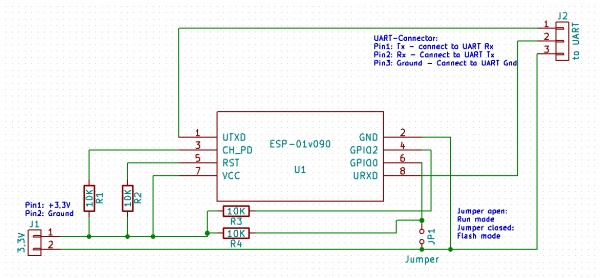
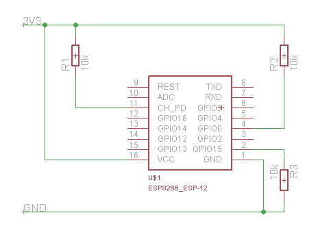
I see 4 x 10k pull up resistors: CH_PD, GPIO0, RST, GPIO2

According to my tests, only CH_PD + GPIO0 are needed to have the ESP to boot correctly. I've even connected CH_PD directly to VCC, because i saw this on many other sites.

Because i want to solder everything on the ESP itself, and also add a capacitor for power, the less components, the easier to solder...
(Imagine the mess with 4 resistors + 1 capacitor :shock: ), here are my questions :

1) Are RST and GPIO2 pullup resistors really needed, and why?

2) Is the resistor on CH_PD needed. Wiring vcc directly would be bad ?

3) Any advice on the capacitor between Gnd and Vcc? Thanks to the guide on the wiki, ia already bought some 10uF tantalum capacitor, just in case. Would they do the job correctly ? Are they really needed (knowing that the relay also have a 10uF capa, but on the 5V rail, just before the LD1117 regulator?

sorry is theses question seem dumb ...i'm a software guy :oops:

Thank you
Last edited by soif on 03 Mar 2018, 12:38, edited 1 time in total.
Soif
-----
Want to update ALL your ESP babies OverTheAir, or backup their settings in ONE simple command, + many other cool features.... Adopt EspBuddy

User avatar
soif
Normal user
Posts: 46
Joined: 20 Feb 2018, 19:11
Location: Solar System
Contact:

Re: Any definitive wiring guide for an ESP-01 1M ?

#2 Post by soif » 03 Mar 2018, 08:30

Any hardware guy to help me? :P
Soif
-----
Want to update ALL your ESP babies OverTheAir, or backup their settings in ONE simple command, + many other cool features.... Adopt EspBuddy

User avatar
vader
Normal user
Posts: 241
Joined: 21 Mar 2017, 17:35

Re: Any definitive wiring guide for an ESP-01 1M ?

#3 Post by vader » 03 Mar 2018, 12:04

GPIO2 = UART Tx during flash programming; GPIO2

CH_PD and RST needs to pulled high for normal operation of the ESP.

User avatar
soif
Normal user
Posts: 46
Joined: 20 Feb 2018, 19:11
Location: Solar System
Contact:

Re: Any definitive wiring guide for an ESP-01 1M ?

#4 Post by soif » 03 Mar 2018, 12:37

Thanks for the reply. 8-)

I just realize that my question was maybe not clear enough : What are the minimal requirements for normal boot operation ?
For flash, I have a usb programmer that do the job just fine.

But for normal operations, I had to wire (not properly pull-up) CH_PD to vcc and also pull-up GPIO0 (if not, no boot)....

hence my questions..
Soif
-----
Want to update ALL your ESP babies OverTheAir, or backup their settings in ONE simple command, + many other cool features.... Adopt EspBuddy

User avatar
vader
Normal user
Posts: 241
Joined: 21 Mar 2017, 17:35

Re: Any definitive wiring guide for an ESP-01 1M ?

#5 Post by vader » 03 Mar 2018, 13:31

See step 3 on this page. It shows a min. HW config....
http://www.instructables.com/id/Getting ... 66-ESP-12/

User avatar
soif
Normal user
Posts: 46
Joined: 20 Feb 2018, 19:11
Location: Solar System
Contact:

Re: Any definitive wiring guide for an ESP-01 1M ?

#6 Post by soif » 03 Mar 2018, 17:13

this link shows the wiring for FLASHING, not for nomal operation (boot from flash) :roll:
Soif
-----
Want to update ALL your ESP babies OverTheAir, or backup their settings in ONE simple command, + many other cool features.... Adopt EspBuddy

User avatar
budman1758
Normal user
Posts: 301
Joined: 15 Apr 2017, 05:13
Location: Riverside CA USA

Re: Any definitive wiring guide for an ESP-01 1M ?

#7 Post by budman1758 » 04 Mar 2018, 09:20

sorry is theses question seem dumb ...i'm a software guy :oops:
No such thing as a dumb question. :mrgreen:

I am not an expert but this works on my ESP-01 units.
CH_PD can be wired direct to 3.3v. I don't use a resistor at all. Have had zero bad experience with that.
RST needs a pull up resistor (10k is fine) because you have to pull to gnd to reset the unit. (restart it). Without a resistor you would have a direct short. If you don't need that functionality you can leave out the resistor. It can float. A switch on the power supply will do the same thing.
GPOI 0 and 2 need to be pulled up for normal boot. You could probably get away with direct 3,3v if you do not use the GPIO for anything. Reason for a 10k resistor is so you can also set them low in software.
As for the capacitor, I'm not sure, I think it has a lot to do with the quality of your input power. I have some -01's without a cap and they have been running fine for months without a reboot. As of this writing they have been up for 162 days. Of course, your mileage may vary. :lol:

Hope this helps
"The glass is twice as big as it needs to be".

User avatar
soif
Normal user
Posts: 46
Joined: 20 Feb 2018, 19:11
Location: Solar System
Contact:

Re: Any definitive wiring guide for an ESP-01 1M ?

#8 Post by soif » 05 Mar 2018, 06:21

Thank you very much for your answer. It's starting to be understandable
I don't need the RST features, so I will let it float.
GPIO0 is needed (and I use it as the relay command) so I will keep the Pull-Up, and keep the CH_PD wired to VCC as you confirm it works fine without a resistor.

Biu what about GPIO2?
Currently it floats, and it boots fine. Would I get trouble if it stay like that ?
Soif
-----
Want to update ALL your ESP babies OverTheAir, or backup their settings in ONE simple command, + many other cool features.... Adopt EspBuddy

User avatar
budman1758
Normal user
Posts: 301
Joined: 15 Apr 2017, 05:13
Location: Riverside CA USA

Re: Any definitive wiring guide for an ESP-01 1M ?

#9 Post by budman1758 » 05 Mar 2018, 07:22

soif wrote: 05 Mar 2018, 06:21 Biu what about GPIO2?
Currently it floats, and it boots fine. Would I get trouble if it stay like that ?
Come to think of it I am not sure about GPIO2. I might have been using a resistor to ensure it was high on boot for a relay.
I would say if it boots fine floating, let it float. It can't really hurt anything.
I think a lot of this pull up or down resistor stuff is just "standard practice". Not always needed but just customary......
Like us mechanics say. "If it ain't broke, Don't fix it". :mrgreen:
"The glass is twice as big as it needs to be".

User avatar
soif
Normal user
Posts: 46
Joined: 20 Feb 2018, 19:11
Location: Solar System
Contact:

Re: Any definitive wiring guide for an ESP-01 1M ?

#10 Post by soif » 05 Mar 2018, 07:52

Sure letting GPIO2 flloat will certainly not heart the ESP, but will it be reliable in the long term?
I prefer rather spending time at start, than repairing stuff later.
If it ain't broke, Don't fix it
This has ALWAYS been by own motto ! 8-)
Soif
-----
Want to update ALL your ESP babies OverTheAir, or backup their settings in ONE simple command, + many other cool features.... Adopt EspBuddy

User avatar
budman1758
Normal user
Posts: 301
Joined: 15 Apr 2017, 05:13
Location: Riverside CA USA

Re: Any definitive wiring guide for an ESP-01 1M ?

#11 Post by budman1758 » 05 Mar 2018, 07:59

soif wrote: 05 Mar 2018, 07:52 Sure letting GPIO2 flloat will certainly not heart the ESP, but will it be reliable in the long term?
I prefer rather spending time at start, than repairing stuff later.
Methinks you will be fine long term. :ugeek:
"The glass is twice as big as it needs to be".

User avatar
soif
Normal user
Posts: 46
Joined: 20 Feb 2018, 19:11
Location: Solar System
Contact:

Re: Any definitive wiring guide for an ESP-01 1M ?

#12 Post by soif » 05 Mar 2018, 08:38

Ok thanks for your experienced opinion. 8-)

so I will certainly end up ONLY wiring CH_PD to VCC + GPIO-0 10k pullup, if nobody else disapprove. :?:

Any advice on the capacitor?
Is my 10uF tantalum one a good choice?
just in case (because I have no oscilloscope to check the power supply).
Soif
-----
Want to update ALL your ESP babies OverTheAir, or backup their settings in ONE simple command, + many other cool features.... Adopt EspBuddy

User avatar
soif
Normal user
Posts: 46
Joined: 20 Feb 2018, 19:11
Location: Solar System
Contact:

Re: Any definitive wiring guide for an ESP-01 1M ?

#13 Post by soif » 10 Mar 2018, 11:15

BTW while searching for other esp related things, I found on this , which seems a reliable source:
http://arduino-esp8266.readthedocs.io/e ... ml#minimal

Minimal boot (for ESP12):
Image

CH_PD + GPIO0 confirmed to be pull-up + ( GPIO15 pulldown should ceraintly be ignored, as it is NOT present on ESP01)
Soif
-----
Want to update ALL your ESP babies OverTheAir, or backup their settings in ONE simple command, + many other cool features.... Adopt EspBuddy

Shardan
Normal user
Posts: 1156
Joined: 03 Sep 2016, 23:27
Location: Bielefeld / Germany

Re: Any definitive wiring guide for an ESP-01 1M ?

#14 Post by Shardan » 10 Mar 2018, 17:02

A 10KOhm from Reset to 3.3V is always a good idea. Some ESP-01 have it in board some rely on the ESP8266's own "weak" pullup.

I'd always add a capacitor as near as possible to +3.3V and Gnd.
I reccomend to electrolytic or tantalum capacitors.
Use a ceramic type (X5R or X7R series). These MLCC capacitors have a much
better performance on high frequencies then other types. 100nF...1µF will do.

For the R3 (GPIO15 -> GND) .... GPIO15 must be pulled down to GND to start the firmware.
I won't ignore this......
Regards
Shardan

SophieDeziel
New user
Posts: 3
Joined: 27 Jun 2018, 20:05

Re: Any definitive wiring guide for an ESP-01 1M ?

#15 Post by SophieDeziel » 27 Jun 2018, 20:26

I found this post (and the wonderful guide) using Google trying to find an answer to a pretty specific question:

To flash the ESP8266-01, I have found that some modules need the GPIO2 pin to be connected to VCC and some others can be left dangling, while in all cases GPIO0 must be connected to ground.

I'm trying to find the reason or a way to identify which modules need to have GPIO2 to be up at boot time to flash. Could it be because of some external factor like power source? I'll be very happy to contribute to the guide with this information.

Shardan
Normal user
Posts: 1156
Joined: 03 Sep 2016, 23:27
Location: Bielefeld / Germany

Re: Any definitive wiring guide for an ESP-01 1M ?

#16 Post by Shardan » 30 Jun 2018, 19:30

It is a somewhat specific problem with ESP-01:

There is a mess of versions, all called ESP-01. (V.1, V.2, V.3, ESP-01S and maybe more)
The types differ a bit with their internal circuits, some have pull-ups other versions miss and so on.

For my own circuits I tend to use external pullup resistors anyways.

Why?

Well, it does not hurt if you add a 10KOhm resistor in parallel to the internal pullup on the board if there is any.
On the other side it makes sure that every version works.

Sure you may connect CH_PD directly to Vcc - prefer a 10KOhm resistor anyways.
When switching power supply on or off voltage spikes may occur for example.
A resistor is a protection for the inputs in that case.

Together with this: Give RST a 10KOhm to Vcc and a capacitor 22µ...47µ to GND.
This keeps the chip on reset for a short moment after powering up. Just make it wait a bit for stable power line.
Even a good power supply is somewhat unpredictable when switched on/off.

You can leave GPIO2 floating, sure. But be aware that the internal on-chip pullup is "weak". External interferences
may influence the input - it needs a well defined "high" level for correct booting. If you really need a resistor depends
on your circuit anyways. If you drive a LCD 2004 display on GPIO 0/2 of an ESP-01 it is usually not necessary: Most display
driver boards have pullups built in

The study books say "don't leave any input floating" for a reason - reliability.
This on one side is pure theory. On the practical side any input involved in startup should have a pull-resistor.
That will give a good reliability for daily use (Besides things like filtering capacitors and such, obviously.... )

Regards
Regards
Shardan

User avatar
grovkillen
Core team member
Posts: 3621
Joined: 19 Jan 2017, 12:56
Location: Hudiksvall, Sweden
Contact:

Re: Any definitive wiring guide for an ESP-01 1M ?

#17 Post by grovkillen » 30 Jun 2018, 20:17

Shardan wrote: 30 Jun 2018, 19:30 ...
You're back! :)
ESP Easy Flasher [flash tool and wifi setup at flash time]
ESP Easy Webdumper [easy screendumping of your units]
ESP Easy Netscan [find units]
Official shop: https://firstbyte.shop/
Sponsor ESP Easy, we need you :idea: :idea: :idea:

SophieDeziel
New user
Posts: 3
Joined: 27 Jun 2018, 20:05

Re: Any definitive wiring guide for an ESP-01 1M ?

#18 Post by SophieDeziel » 10 Jul 2018, 20:25

Thank you so much Shardan!

Your explanations are super clear. Not only there is the "how" but also the "why". I'll follow your advices with the pull-up resistors and also the capacitor.

Post Reply

Who is online

Users browsing this forum: No registered users and 20 guests