Page 1 of 1
can not get BMP280 to work
Posted: 14 Feb 2020, 18:43
by GravityRZ
i have a BMP280 connected to a Wemos D1 mini running latest ESPeasy mega software
i am using the BMX280 plugin
VCC on 3.3V
GND op GND
SCL op D1
SDA op D2
CSB 3.3V (to select i2C)
SD0 GND (to select 0x76 adres)
somehow i do net get any data in
hardware page is also on default
SDA GPIO-4 D2
SCL GPIO-5 D1
in the log it states
BMx280 unable to detect chip id
can anybody see what i might be doing wrong?
Re: can not get BMP280 to work
Posted: 14 Feb 2020, 22:40
by Domosapiens
Did you try:
Tools / I2C San ?
Did it discover the module ??
At 0x76 address ??
Re: can not get BMP280 to work
Posted: 14 Feb 2020, 22:59
by GravityRZ
no it did not discover the module.
also i tried putting the module to 0x77 (connect SDO to 3.3v) but this did not help either.
really strange
tried other wemos module but the same result so the problem is either a faulty module or something i missed
Re: can not get BMP280 to work
Posted: 14 Feb 2020, 23:48
by TD-er
Make sure the set pins for using I2C are the ones you try to use.
See the "Hardware" tab in the web interface.
It is best to use these:
- GPIO-4 (D2) for SDA
- GPIO-5 (D1) for SCL
Most BMP280/BME280 boards have no need to set them to I2C mode.
Make sure the board you're using is for 3v3. On AliExpress there are lots of batches sold for 5V only.
Re: can not get BMP280 to work
Posted: 15 Feb 2020, 08:34
by GravityRZ
it is this one.
got it from opencircuits (expensive but fast shipping)
so you are saying VCC should be connected to 5V (on the site it states max 3.6v)
as far as i can tell there is no standard for VCC
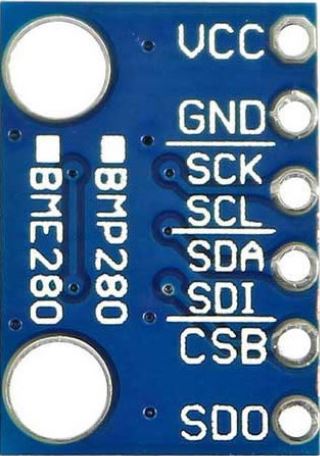
- bmp280.JPG (38.06 KiB) Viewed 15164 times
Re: can not get BMP280 to work
Posted: 15 Feb 2020, 10:41
by Shardan
If the picture shows the board you use exactly I won't use 5V.
I can't see any voltage regulator, just some capacitors and resistors.
Following datasheet the BMP280 has a max. Vcc of 3,6V!
For I²C the datasheet shows this circuit:
.

- BMP280-I2C.jpg (151.62 KiB) Viewed 15141 times
.
Many modules connect Vdd and Vddio internaly, that is usual and no problem.
(Yes, they call it Vdd instead of Vcc. Names.....)
So for the standard I²C address SDO should be connected to GND, for alternative address to Vcc.
For using I²C the CSB input should be connected to Vcc.
As I have no schematic of that module i can't see if inputs are pulled up or down with the
resistors so external connection might lead to a better result.
The full datasheet can be found here:
https://ae-bst.resource.bosch.com/media ... -DS001.pdf
Re: can not get BMP280 to work
Posted: 15 Feb 2020, 10:53
by GravityRZ
thanks
i am going to inspect the module under a magnifying glass because it is hooked up exactly like you said.
i even changed address to 0x77 to make sure there is not a bug in the plugin which defaults to that(both 0x76 and 0x77 do not work)
if i bought this one at aliexpress i could live with that but i paid EUR 3,50 ex shipping so for that price i really need it to work
Re: can not get BMP280 to work
Posted: 15 Feb 2020, 13:07
by GravityRZ
got it working.
i noticed a connection which was not 100% ok
under a microscope i was able to do some soldering on the pcb.
also once i got it working i tested by removing the SDO and CSB connection, still working and defaults to I2C and 0x76
thanks for the help