I have seen that PIR sensor is/was going to be added as a device.
Is this still in development or canceled?
https://www.domoticz.com/forum/viewtopi ... 5&start=20
PIR sensor
Moderators: grovkillen, Stuntteam, TD-er
Re: PIR sensor
+1 for the PIR (5v/3.3v) (as switch?)

Re: PIR sensor
And what is this PIR-device in ESPEasy supposed to do ?highroller wrote:I have seen that PIR sensor is/was going to be added as a device.
Is this still in development or canceled?
https://www.domoticz.com/forum/viewtopi ... 5&start=20
In principle this is a ordinary switch that is 'ON' as long as there is a moving object in front of it.
Do you expect that when it is a ESPEasy-device it can distinguish between a human, a dog, a cat and a zombie ?
Re: PIR sensor
that would be ESPeasy-like!costo wrote: Do you expect that when it is a ESPEasy-device it can distinguish between a human, a dog, a cat and a zombie ?
but the pir device has resitors for time/duration and sensitivity. in worst cases it triggers in really short intervals again.
i think i could be helpful to expand the "switch" to a "PIR" with some 'debounce'-timer. not more, i guess.
but i would no wonder if the devs manage a new devicte to
costo wrote: distinguish between a human, a dog, a cat and a zombie ?
-
highroller
- Normal user
- Posts: 31
- Joined: 09 Feb 2016, 22:16
Re: PIR sensor
Dont know if i am doing it wrong but when using a PIR as a switch (normal, active high, active low) i get an "on" when movement is registered, and have to move again for it to send the "off" command.costo wrote:And what is this PIR-device in ESPEasy supposed to do ?highroller wrote:I have seen that PIR sensor is/was going to be added as a device.
Is this still in development or canceled?
https://www.domoticz.com/forum/viewtopi ... 5&start=20
In principle this is a ordinary switch that is 'ON' as long as there is a moving object in front of it.
Do you expect that when it is a ESPEasy-device it can distinguish between a human, a dog, a cat and a zombie ?
Re: PIR sensor
jeah,
but in my gira-homeserver i have configured a longer timer than the PIR has itself,
so that my lights stay on over this longer duration. without going off after the pir-timer. or flicker off...
i could do this again with my homeserver and ESPeasy, but it would be nice, if i configure the PIR for very short period,
so it permanently retrigger on small movements, but do only send an on/off over MQTT in an longer period.
wich than could be a timer in the device section for the PIR on ESP...
just a very,very, small difference to a manual on/off-switch, i guess..
-
highroller
- Normal user
- Posts: 31
- Joined: 09 Feb 2016, 22:16
Re: PIR sensor
When i try to add a PIR as normal switch the ESP sends on/off state every second.
Even if i put the sensor in a small box (with no movement) it toggles between on and off. Is it any settings i can adjust or is my PIR broken?
And the timer settings on the PIR itself. Is this for "When motion is detected for X seconds send signal that is PIR activated" or "WHen movement is detected send PIR activated signal for X seconds"?
Re: PIR sensor
highroller wrote: Is it any settings i can adjust or is my PIR broken?
And the timer settings on the PIR itself.
-->
https://learn.adafruit.com/pir-passive- ... sing-a-pir
Re: PIR sensor
According to me, it should take care of the control system. No sensor itself.tozett wrote:jeah,
but in my gira-homeserver i have configured a longer timer than the PIR has itself,
so that my lights stay on over this longer duration. without going off after the pir-timer. or flicker off...
i could do this again with my homeserver and ESPeasy, but it would be nice, if i configure the PIR for very short period,
so it permanently retrigger on small movements, but do only send an on/off over MQTT in an longer period.
wich than could be a timer in the device section for the PIR on ESP...
just a very,very, small difference to a manual on/off-switch, i guess..
Re: PIR sensor
I agree with tozett here, it could be an option 
Re: PIR sensor
Have you solved that problem?highroller wrote: ↑10 Mar 2016, 12:10 When i try to add a PIR as normal switch the ESP sends on/off state every second.
Even if i put the sensor in a small box (with no movement) it toggles between on and off. Is it any settings i can adjust or is my PIR broken?
And the timer settings on the PIR itself. Is this for "When motion is detected for X seconds send signal that is PIR activated" or "WHen movement is detected send PIR activated signal for X seconds"?
I "sometimes" get the very same effect with a nodeMCU hardware and ESPEasy.
I can't put the finger on why it happens, but when it happens, not even a reboot can stop it. I therefore doubt it's the ESPeasy...
I think it has something to do with the VCC to the PIR. The effect happens more often, when I connect VCC of the PIR to the 3.3V from the nodeMCU.
On the other hand, it rarely happens, when I connect the PIR's VCC to the nodeMCU's Vin - which is the +5V from the USB power supply.
Due to the fact that the PIR has a 3.3V converter on-board, the 3.3V from the nodemCU may be too low for the PIR, wich may lead to that effect...
Can someone please
a) confirm this?
b) give an alternate solution for the PIR's VCC problem?
thanks in advance!
ohuf.

Re: PIR sensor
1. search the forum for pir false positive, there is some info.ohuf wrote: ↑07 Mar 2017, 23:22Have you solved that problem?highroller wrote: ↑10 Mar 2016, 12:10 When i try to add a PIR as normal switch the ESP sends on/off state every second.
Even if i put the sensor in a small box (with no movement) it toggles between on and off. Is it any settings i can adjust or is my PIR broken?
And the timer settings on the PIR itself. Is this for "When motion is detected for X seconds send signal that is PIR activated" or "WHen movement is detected send PIR activated signal for X seconds"?
I "sometimes" get the very same effect with a nodeMCU hardware and ESPEasy.
I can't put the finger on why it happens, but when it happens, not even a reboot can stop it. I therefore doubt it's the ESPeasy...
I think it has something to do with the VCC to the PIR. The effect happens more often, when I connect VCC of the PIR to the 3.3V from the nodeMCU.
On the other hand, it rarely happens, when I connect the PIR's VCC to the nodeMCU's Vin - which is the +5V from the USB power supply.
Due to the fact that the PIR has a 3.3V converter on-board, the 3.3V from the nodemCU may be too low for the PIR, wich may lead to that effect...
Can someone please
a) confirm this?
b) give an alternate solution for the PIR's VCC problem?
thanks in advance!
ohuf.
2. connecting vcc of pir to 3.3v. as you corectly mentioned, the pir has its own power regulator. it needs 4,8-12v to deliver stable 3.3v. this can be bypassed by connecting to a different pin/solder pad, then supply can be 3.3v
3. apparently soldering a cap over pin 12+13 of the bis-ic of the pir helps with rf interference/power dips caused by esp tx burst
4. the rf interference can be reduced by shielding (tin foil for ex) and moving the pir away from the esp.
5. changing sunlight also causes false positives
i destroyed one pir when attempting step 3...
the only thing that really helps for me is at least 20cm distance between pir and esp... put pir in seperate box and run 50cm of cable to your esp box.
Domoticz on Raspi 2 -- 14 ESP units (hacked Sonoff,NodeMCUs, Wemos, self-built units) running with RC140- Mega 2.0.0 dev8
-
MortenCopenhagen
- New user
- Posts: 2
- Joined: 14 Apr 2017, 21:23
Re: PIR sensor
Hi This is my first post.
May I suggest that you take a look at this video:
https://www.youtube.com/watch?v=jpjfVc-9IrQ&t=534s
This guy had similar problems with stability of his PIR sensors but found that longer wires helped and he suspects that noise from the ESP can disturb the pir sensor. Also he found a PIR senser that always works. See http://geni.us/WBKyxhx and the other links unders his video.
Cheers
Re: PIR sensor
Hello guys,
the last hours i did some testing with a nodeMCU/ESPEasy and one of these qusetionable PIR modules.
This one, exactly:
https://images-na.ssl-images-amazon.com ... SX355_.jpg
I've chosen this one because sensivity, hold time and retrigger is setable.
I did just a breadboard test and i can confirm the "on/off/on/off" problem.
But i can confirm that the problem is not a EMI-problem (interferences from HF) too.
First i connected the PIR as usual, +3,3V from nodeMCU, GPIO and ground. On/off/on/off.....
Second i connected a separate 5V power supply to the PIR - same.
Then i put a transistor with a LED on the output of the PIR and switched off the nodeMCU - modul works perfectly.
At last i connected back the nodeMCU but leaving the transistor with LED in the circuit - surprise, surprise, it works.
It works even when the PIR is laying on the ESP's antenna (ingore the WeMos above, it's just another testing):
.
.
Yes, even that works!
It seems the PIR misses a pull up resistor and the built-in of the ESP is not suitable for what reason ever.
My last try was a 10 KOhm Resistor from +3,3V to the output of the PIR. It works as wanted that way.
If the chip on the sensor has just an open collector output this would leave the GPIO between "low" and "undefined"
which may generate unpredictable behaviour.
Hope that helps
Regards and Happy Easter Days
Shardan
PS: I should mention:
I tested both variants, with and without a capacitor on pin12 & 13, both work.
Settings: shortest delay, highest sensivity, jumper to the corner of the PCB (not as shown in the picture).
S.
the last hours i did some testing with a nodeMCU/ESPEasy and one of these qusetionable PIR modules.
This one, exactly:
https://images-na.ssl-images-amazon.com ... SX355_.jpg
I've chosen this one because sensivity, hold time and retrigger is setable.
I did just a breadboard test and i can confirm the "on/off/on/off" problem.
But i can confirm that the problem is not a EMI-problem (interferences from HF) too.
First i connected the PIR as usual, +3,3V from nodeMCU, GPIO and ground. On/off/on/off.....
Second i connected a separate 5V power supply to the PIR - same.
Then i put a transistor with a LED on the output of the PIR and switched off the nodeMCU - modul works perfectly.
At last i connected back the nodeMCU but leaving the transistor with LED in the circuit - surprise, surprise, it works.
It works even when the PIR is laying on the ESP's antenna (ingore the WeMos above, it's just another testing):
.
- PIR.jpg (2.98 MiB) Viewed 23454 times
Yes, even that works!
It seems the PIR misses a pull up resistor and the built-in of the ESP is not suitable for what reason ever.
My last try was a 10 KOhm Resistor from +3,3V to the output of the PIR. It works as wanted that way.
If the chip on the sensor has just an open collector output this would leave the GPIO between "low" and "undefined"
which may generate unpredictable behaviour.
Hope that helps
Regards and Happy Easter Days
Shardan
PS: I should mention:
I tested both variants, with and without a capacitor on pin12 & 13, both work.
Settings: shortest delay, highest sensivity, jumper to the corner of the PCB (not as shown in the picture).
S.
Regards
Shardan
Shardan
Re: PIR sensor
Hi ShardanShardan wrote: ↑14 Apr 2017, 23:57 Hello guys,
the last hours i did some testing with a nodeMCU/ESPEasy and one of these qusetionable PIR modules.
This one, exactly:
https://images-na.ssl-images-amazon.com ... SX355_.jpg
I've chosen this one because sensivity, hold time and retrigger is setable.
I did just a breadboard test and i can confirm the "on/off/on/off" problem.
But i can confirm that the problem is not a EMI-problem (interferences from HF) too.
First i connected the PIR as usual, +3,3V from nodeMCU, GPIO and ground. On/off/on/off.....
Second i connected a separate 5V power supply to the PIR - same.
Then i put a transistor with a LED on the output of the PIR and switched off the nodeMCU - modul works perfectly.
At last i connected back the nodeMCU but leaving the transistor with LED in the circuit - surprise, surprise, it works.
It works even when the PIR is laying on the ESP's antenna (ingore the WeMos above, it's just another testing):
.
PIR.jpg
.
Yes, even that works!
It seems the PIR misses a pull up resistor and the built-in of the ESP is not suitable for what reason ever.
My last try was a 10 KOhm Resistor from +3,3V to the output of the PIR. It works as wanted that way.
If the chip on the sensor has just an open collector output this would leave the GPIO between "low" and "undefined"
which may generate unpredictable behaviour.
Hope that helps
Regards and Happy Easter Days
Shardan
PS: I should mention:
I tested both variants, with and without a capacitor on pin12 & 13, both work.
Settings: shortest delay, highest sensivity, jumper to the corner of the PCB (not as shown in the picture).
S.
So far I can confirm your trials. I have three units running inside the house with PIR with longer cables attached, they seem fine (2xnodemcu + wemos d1 pro mini). However the outside unit (also nodemcu) has been giving me trouble... lots of chaotic behavious like discribed in the post. It seemed to be worse during the day than at night (domitcz log) . it was also the only unit with the PIR in the same housing as esp. So I tried to extend the cable.
However , this did not make a difference, still chaotic behaviour. I then soldered an additional 10K Ohm Pull-up-Resistor as per your advice, and , touch wood , so long it is running stable. I had stable days before, but tomorrow in the daylight will show for sure. Will keep you posted
Thanks and happy Easters
Domoticz on Raspi 2 -- 14 ESP units (hacked Sonoff,NodeMCUs, Wemos, self-built units) running with RC140- Mega 2.0.0 dev8
Re: PIR sensor
Hello toffel960,
i'm still monitoring my breadboard since yesterday and it's behaving nice up to now.
Following the datasheet's schematic https://cdn-learn.adafruit.com/assets/a ... SS0001.pdf the HC-SR501 should not have an open-collector output so there shouldn't be a "undefined" state. So i can't explain atm why the resistor seems to work. (To be honest something i can't stand)
Anyways, thanks for confirming that it not only works on my higgledy-piggledy breadboard
Happy Easter to all forum readers
Shardan
Last edited by Shardan on 16 Apr 2017, 17:16, edited 1 time in total.
Regards
Shardan
Shardan
Re: PIR sensor
Hi Shardan,
Very interesting findings of you and I tried to figure out a reason.
The link you provided has an error it should be : https://cdn-learn.adafruit.com/assets/a ... SS0001.pdf.
Looking at this pdf it seems to be a datasheet for the BISS001 and at the end a typical application schematic. No reference to the SR-HC501 module in this document.
Another link https://www.mpja.com/download/31227sc.pdf claims to present the real schematic of the HC-SR501 PIR module.
I have a module like this but am away from home so cannot check my module's output details.
The big difference seems that in the 'real' hc-sr501 there is nothing connected to the Vo output pin, just a series resistor of 2k2 to the output connector.
In the typical BIS001 application there is a series resistor of 2k2 and then a NPN output transistor.
So in a real application Vo is connected to resistor (1k) in series with a (base-emitter) diode to ground. So the output is effectively pulled down to <1 volt. Maybe when leaving the output of the module open or loading it with a high impedance input of a ESP with a weak pullup the BISS001 is not feeling comfortable.
It could be that there is some sort of feedback inside the BISS001 chip, leaving the output unloaded or weakly pulled up causes the instability.
Re: PIR sensor
Hello Costo,
i know that. Just it's the only datasheet for the chip itself i've found. The schematic is - besides the additional transistor - same with the PIR module.
Well, as far as one can trust the schematics found in the net . My modules have an 1KOhm serial in the output.
Due to the schematic in the datasheet it can't be an open collector output. In case of an open collector output the transistor would not get a positive voltage to open.
I took a bare module and put my digiscope at the output. That says it has clean voltage output. The supply voltage on the board is clean too.
What i can see is a somewhat high impedance on the output.
Just the output connected to the scope says 0V for low and around 3V for high.
If i put a 10K resistor from output to ground i get 0V for low and 2,9V for high.
The same resistor put between out and +5V (5V is a bit unfair, i know ) gives 3,6V for high and 1V for low.
According to those values the output impedance including serial resistor is around 2,5KOhm for "low" and about 25KOhm for "high".
This "high" impedance might be the reason for the sensivity against HF interferences.
Happy Easter
Regards
Shardan
PS: Link is ok now.
i know that. Just it's the only datasheet for the chip itself i've found. The schematic is - besides the additional transistor - same with the PIR module.
Well, as far as one can trust the schematics found in the net
Due to the schematic in the datasheet it can't be an open collector output. In case of an open collector output the transistor would not get a positive voltage to open.
I took a bare module and put my digiscope at the output. That says it has clean voltage output. The supply voltage on the board is clean too.
What i can see is a somewhat high impedance on the output.
Just the output connected to the scope says 0V for low and around 3V for high.
If i put a 10K resistor from output to ground i get 0V for low and 2,9V for high.
The same resistor put between out and +5V (5V is a bit unfair, i know
According to those values the output impedance including serial resistor is around 2,5KOhm for "low" and about 25KOhm for "high".
This "high" impedance might be the reason for the sensivity against HF interferences.
Happy Easter
Regards
Shardan
PS: Link is ok now.
Regards
Shardan
Shardan
Re: PIR sensor
Just a little update, the PIR outside the house is running stable the third day now. I updated the wiki concerning PIR under switch. I think many newbies don't understand that every sensor that gives a digital (1/0) output can be used as switchShardan wrote: ↑16 Apr 2017, 17:15 Hello Costo,
i know that. Just it's the only datasheet for the chip itself i've found. The schematic is - besides the additional transistor - same with the PIR module.
Well, as far as one can trust the schematics found in the net
Due to the schematic in the datasheet it can't be an open collector output. In case of an open collector output the transistor would not get a positive voltage to open.
I took a bare module and put my digiscope at the output. That says it has clean voltage output. The supply voltage on the board is clean too.
What i can see is a somewhat high impedance on the output.
Just the output connected to the scope says 0V for low and around 3V for high.
If i put a 10K resistor from output to ground i get 0V for low and 2,9V for high.
The same resistor put between out and +5V (5V is a bit unfair, i know
According to those values the output impedance including serial resistor is around 2,5KOhm for "low" and about 25KOhm for "high".
This "high" impedance might be the reason for the sensivity against HF interferences.
Happy Easter
Regards
Shardan
PS: Link is ok now.
Domoticz on Raspi 2 -- 14 ESP units (hacked Sonoff,NodeMCUs, Wemos, self-built units) running with RC140- Mega 2.0.0 dev8
Re: PIR sensor
I'm testing now and it looks really good.
a 220nf on pin 12 and 13 look at the picture.
It's simple to solder.
a 220nf on pin 12 and 13 look at the picture.
It's simple to solder.
- Attachments
-
- magnifier_20170418_203950.png (1.38 MiB) Viewed 24478 times
Re: PIR sensor
Thanks, I was going for the smd-ic
Domoticz on Raspi 2 -- 14 ESP units (hacked Sonoff,NodeMCUs, Wemos, self-built units) running with RC140- Mega 2.0.0 dev8
Re: PIR sensor
dear all,
Someone have a pir working with a ESP breadboard?
http://linksprite.com/wiki/index.php5?t ... controller
Or can someone tell me how i must setup this option.
The esprelaisboard have 3 pins:
NC normaly closed
COM
NO normaly open
So what port do need to set the pir..
And is it perhasp possible to use multiple motionsensors on 1 port [ gpio] ?
Re: PIR sensor
Hello Dylantje,
The NC/COM/NO are relay contacts for switching load.
You may switch on and of a PIR, but these ports are not able to work as an input from the PIR.
A relay is just a switch, pushed by a coil.The contacts say:
If GPIO is off the NC-->COM are connected
IF GPIO is on the NO-->COM are connected.
If you want to connect a PIR as a sensor to the linknode there are two ways.
One possibility is soldering a wire to one of the unused GPIO ports (as far as i remember GPIO 2 and GPIO 9 with the LinkNode R8).
The second possibility is using the TX/RX-connector (GPIO 1 & 3) on the board. Before using them switch the serial monitoring off in the advanced tab.
Another solution might be to use a separate small ESP or easier a WeMOS D1 Mini or NodeMCU for the sensor and setup the global sync to get the PIR data to the LinkNode.
Multiple PIR on one GPIO?
Not directly. The usual PIR sensors with the BSS2xxx chip have an active output so connecting them together would lead to shortcircuits possibly damaging the PIRs.
But it should be possible to use a "nor" gate like a 74HC4002 to tie them together.
A circuit for that looks like this:
.
.
The 3,3V and the 5V can be taken from the LinkNode.
It has two outputs. Out = active "high", inverted out = active "low".
Two hints:
Unused inputs must be connected to ground!
The 4002 itself is very sensitive against electrostatic discharge. Use a socket, do not solder it directly into the circuit.
Leave it in it's package, put it into the socket as very last step.
I reccomed doing this on a small antistatic foam mat like this:
https://www.conrad.de/de/esd-schaumstof ... 37410.html
Regards
Shardan
The NC/COM/NO are relay contacts for switching load.
You may switch on and of a PIR, but these ports are not able to work as an input from the PIR.
A relay is just a switch, pushed by a coil.The contacts say:
If GPIO is off the NC-->COM are connected
IF GPIO is on the NO-->COM are connected.
If you want to connect a PIR as a sensor to the linknode there are two ways.
One possibility is soldering a wire to one of the unused GPIO ports (as far as i remember GPIO 2 and GPIO 9 with the LinkNode R8).
The second possibility is using the TX/RX-connector (GPIO 1 & 3) on the board. Before using them switch the serial monitoring off in the advanced tab.
Another solution might be to use a separate small ESP or easier a WeMOS D1 Mini or NodeMCU for the sensor and setup the global sync to get the PIR data to the LinkNode.
Multiple PIR on one GPIO?
Not directly. The usual PIR sensors with the BSS2xxx chip have an active output so connecting them together would lead to shortcircuits possibly damaging the PIRs.
But it should be possible to use a "nor" gate like a 74HC4002 to tie them together.
A circuit for that looks like this:
.
- OR-Gate for PIR.jpg (38.69 KiB) Viewed 24398 times
The 3,3V and the 5V can be taken from the LinkNode.
It has two outputs. Out = active "high", inverted out = active "low".
Two hints:
Unused inputs must be connected to ground!
The 4002 itself is very sensitive against electrostatic discharge. Use a socket, do not solder it directly into the circuit.
Leave it in it's package, put it into the socket as very last step.
I reccomed doing this on a small antistatic foam mat like this:
https://www.conrad.de/de/esd-schaumstof ... 37410.html
Regards
Shardan
Regards
Shardan
Shardan
Re: PIR sensor
Dear Shardan...
Thanks for your explane..... Only this i higher math for me.
I am just a bricklayer......
Still get no stable pir working.
Everything i try give a on /off on/off motion sensor..
First i need to get 1 stable pir....
When i do have 1 stable i think i must be happy..
Thanks for your explane..... Only this i higher math for me.
I am just a bricklayer......
Still get no stable pir working.
Everything i try give a on /off on/off motion sensor..
First i need to get 1 stable pir....
When i do have 1 stable i think i must be happy..
Re: PIR sensor
Hello Dylantje,
put a resistor of 10K-Ohm from +3,3V to the Data Out / GPIO-Pin you use for PIR.
Regards
Shardan
put a resistor of 10K-Ohm from +3,3V to the Data Out / GPIO-Pin you use for PIR.
Regards
Shardan
Regards
Shardan
Shardan
Re: PIR sensor
Dear Sharan...
I did try that only no luck @ all.
Did try 4 types motions sensors...
And i use different Gpio...
No stable motion ....
GPIO 0 and 16.. both work fine with a DHT.
I try this sensors:
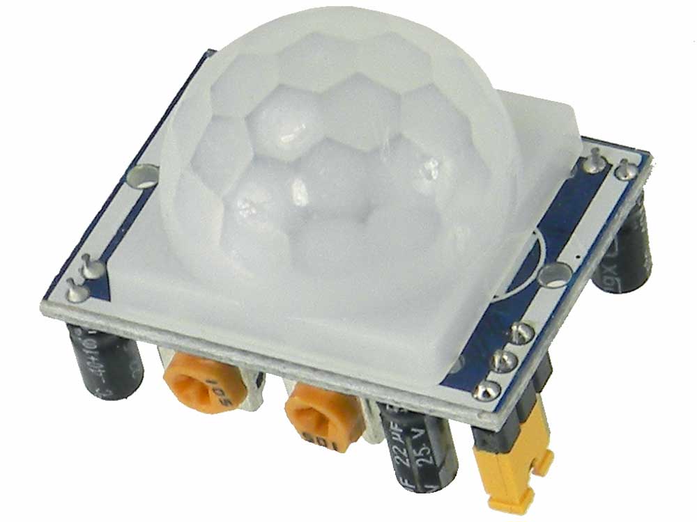
http://www.mpja.com/images/31227-large.jpg
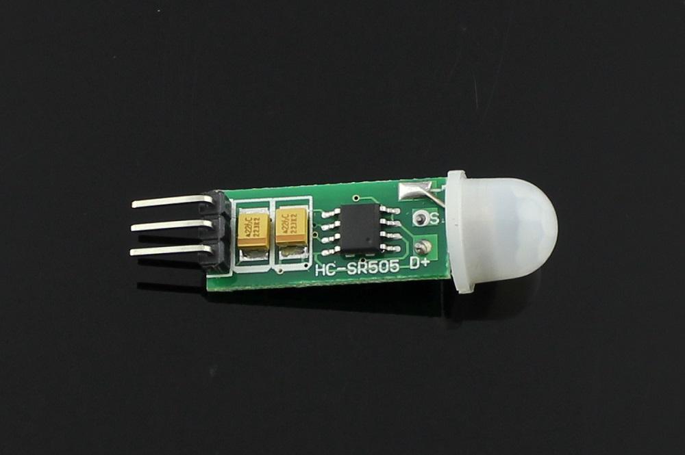
http://arduinolearning.com/wp-content/u ... R505-2.jpg
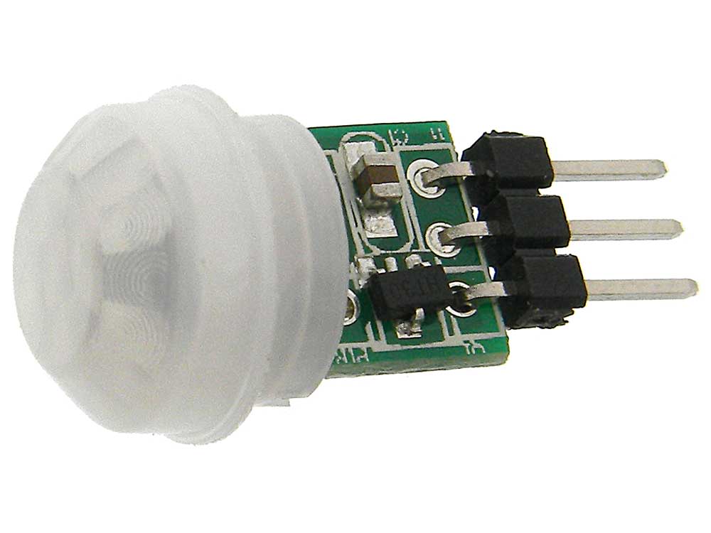
https://s-media-cache-ak0.pinimg.com/56 ... cc20b4.jpg
http://www.mpja.com/images/32061-large.jpg
And a other one i have @ home.
I try different gpio with and without a resistor...
Only no stable working motion..
Did buy some others...
And i see in the wiki there is a other dgital motion sensor.
Only i use on this board the gpio for switching.
https://www.tindie.com/products/nEXT_EV ... utomation/
So if someone have a other solution for a motion or something like that.
Perhaps a line when you walk tough a signal or something like that..
Re: PIR sensor
I'm wondering why it is not working.
I just have soldered a server room sensor prototype that includes a PIR sensor and tested it:
.
.
It works quite nice without issues.
The PIR runs on 5V, the output is directly connected to GPIO2.
Regards
Shardan
I just have soldered a server room sensor prototype that includes a PIR sensor and tested it:
.
- USIR-Sensor Frontside.jpg (84.1 KiB) Viewed 24299 times
- USIR-Sensor-Backside.jpg (46.26 KiB) Viewed 24299 times
It works quite nice without issues.
The PIR runs on 5V, the output is directly connected to GPIO2.
Regards
Shardan
Regards
Shardan
Shardan
Re: PIR sensor
mmm 5 volt....
Do i need a power up system...??
Output is 3,3v...from this board
Do i need a power up system...??
Output is 3,3v...from this board
Re: PIR sensor
The sensor i used has it's own voltage regulator from 5...15 Volts to 3,3V.
i can't say what the small sensors use, i didn't test them yet.
The PIR's with their own regulator will not work easily with 3,3V as the regulator needs some volts for itself to work.
This so called "Drop Out Voltage" usually is about 1V or higher, so it needs at least 4,5 V to work.
As i need 5V anyways for the ultrasonic distance sensor i use a 5V power supply and placed a voltage regulator for the ESP-12E on the board.
You can see it on the second picture below the ESP, the black square is a LF33 regulator.
If i may suggest, give it a try with a 5V-power supply for the PIR and see if it works.
Be carefull, the small PIR's may give 5V at the output, this will damage the ESP.
The big ones (your pictures 1 and 3) give 3,3V output, that's safe.
Regards
Shardan
Regards
Shardan
Shardan
Re: PIR sensor
You can try and bypass the onboard voltage regulator of the PIR and supply 3.3V directly http://randomnerdtutorials.com/modifyin ... k-at-3-3v/Shardan wrote: ↑27 Apr 2017, 22:50 The sensor i used has it's own voltage regulator from 5...15 Volts to 3,3V.
i can't say what the small sensors use, i didn't test them yet.
The PIR's with their own regulator will not work easily with 3,3V as the regulator needs some volts for itself to work.
This so called "Drop Out Voltage" usually is about 1V or higher, so it needs at least 4,5 V to work.
As i need 5V anyways for the ultrasonic distance sensor i use a 5V power supply and placed a voltage regulator for the ESP-12E on the board.
You can see it on the second picture below the ESP, the black square is a LF33 regulator.
If i may suggest, give it a try with a 5V-power supply for the PIR and see if it works.
Be carefull, the small PIR's may give 5V at the output, this will damage the ESP.
The big ones (your pictures 1 and 3) give 3,3V output, that's safe.
Regards
Shardan
Domoticz on Raspi 2 -- 14 ESP units (hacked Sonoff,NodeMCUs, Wemos, self-built units) running with RC140- Mega 2.0.0 dev8

Re: PIR sensor
as the onboard LDO is also connected to another 3 pins strip in my case, I found that this instructions work equally well, and they don't need any soldering, just putting the Dupont wire on a different pin where the 3.3V line is. Much simpler!toffel969 wrote: ↑28 Apr 2017, 09:50 You can try and bypass the onboard voltage regulator of the PIR and supply 3.3V directly http://randomnerdtutorials.com/modifyin ... k-at-3-3v/
http://techgurka.blogspot.com/2013/05/c ... otion.html
Luca
Re: PIR sensor
mmm
Other problem...
Set my board in a reboot loop. witouth options? see no webgui, board is starting en
Was playing with the settings...
Is there a way i can return to factory or ... other options. to place a backup back..?
Thanks again!
xxx
Other problem...
Set my board in a reboot loop. witouth options? see no webgui, board is starting en
Was playing with the settings...
Is there a way i can return to factory or ... other options. to place a backup back..?
Thanks again!
xxx
Re: PIR sensor
Hello Dylantje,
Anything connected to the ESP? If so, remove all connections to GPIO's.
Can you still connect vie serial to monitor what the ESP does?
Then use the Arduino IDE or ESPlorer ( https://esp8266.ru/esplorer/ )
and send the comand RESET to the ESP shortly before it reboots.
This resets the whole configuration.
Sometimes reflashing the firmware might help.
More rude: Flash a nodeMCU firmware, then reflash ESPEasy.
Flashing should work even if the ESP is in a boot loop.
Regards
Shardan
Regards
Shardan
Shardan
Re: PIR sensor
Thnaks
I did a hard reset
tx and rx connect when i bood.
Backup back and running like a new ..
thanks for the support//
I did a hard reset
tx and rx connect when i bood.
Backup back and running like a new ..
thanks for the support//
Who is online
Users browsing this forum: No registered users and 47 guests