Moderators: grovkillen, Stuntteam, TD-er
-
the cosmic gate
- Normal user
- Posts: 103
- Joined: 14 Nov 2015, 20:17
#1
Post
by the cosmic gate » 12 Jun 2016, 19:28
Trying to build a ATO using some floating sensors :
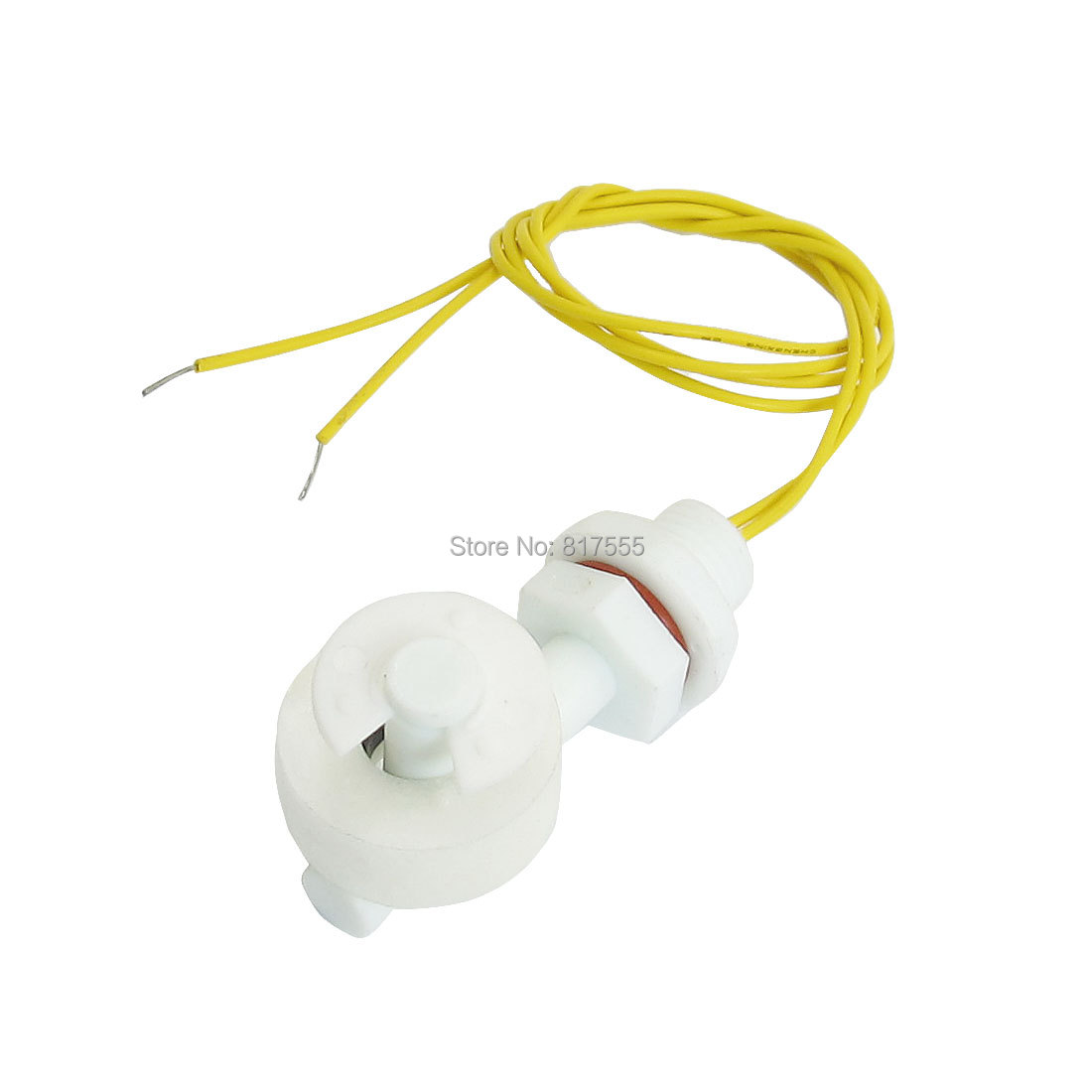
I already tried to connect this some different ways but what's the way to connect these ?
The ways in connect them aren't stable enough and gives sometimes false 0 / 1's
-
CoolWombat
- Normal user
- Posts: 30
- Joined: 31 Oct 2015, 08:00
#2
Post
by CoolWombat » 14 Jun 2016, 13:51
How are you connecting it? Looking at the picture halfway down the page -
http://www.aliexpress.com/item/2016-Hot ... af18292000
It seems like the switch is open when the disc is close to the mounting shaft. If you install it based on the picture you show (or the two bottom pictures in the link above) ie: with the device pointing up, then the switch will be closed when the water is full and pushed the disc up and away from the shaft. Is that what you're seeing? Are you saying that it intermittently gives false reading?
-
Dylantje
- Normal user
- Posts: 255
- Joined: 11 Oct 2015, 16:51
#3
Post
by Dylantje » 14 Jun 2016, 20:50
How did you wiring to the esp?
-
the cosmic gate
- Normal user
- Posts: 103
- Joined: 14 Nov 2015, 20:17
#4
Post
by the cosmic gate » 14 Jun 2016, 22:07
Dylantje wrote:How did you wiring to the esp?
Building this on a prototype board.
And experimented with : connecting + voltage on the floater and the singal cable to the sonoff so when the floater is "on" there 5v + to the signal , also tried the same with the GND, connected some LED to see if there "on" not.
So what's " the way" tI use or connect these switches
-
Dylantje
- Normal user
- Posts: 255
- Joined: 11 Oct 2015, 16:51
#5
Post
by Dylantje » 15 Jun 2016, 07:07
Perhaps this is the problem:

- ScreenShot020.jpg (7.71 KiB) Viewed 9099 times
-
the cosmic gate
- Normal user
- Posts: 103
- Joined: 14 Nov 2015, 20:17
#6
Post
by the cosmic gate » 15 Jun 2016, 10:28
Dylantje wrote:Perhaps this is the problem:
ScreenShot020.jpg
Uhhhm why ? These are maximum currents, but how to use these as a on/off switch using the 5v current from the esp (sonoff) ?
-
CoolWombat
- Normal user
- Posts: 30
- Joined: 31 Oct 2015, 08:00
#7
Post
by CoolWombat » 15 Jun 2016, 13:17
As you can enable an internal "pull Up" resistor on the ESP, it will be easier to connect one wire from the switch to one of the GPIO and then other wire to ground/0V. I have a similar config for my garage door sensor using a reed switch connected to GPIO-12 and a magnet -

- switch.jpg (57.5 KiB) Viewed 9080 times
So when the switch is on/closed, GPIO-12 goes low. I am going to guess that the switch you have will be similar with a reed switch at the end of the shaft and that round float has a magnet on it.
-
the cosmic gate
- Normal user
- Posts: 103
- Joined: 14 Nov 2015, 20:17
#8
Post
by the cosmic gate » 28 Aug 2016, 08:57
CoolWombat wrote:As you can enable an internal "pull Up" resistor on the ESP, it will be easier to connect one wire from the switch to one of the GPIO and then other wire to ground/0V. I have a similar config for my garage door sensor using a reed switch connected to GPIO-12 and a magnet -
switch.jpg
So when the switch is on/closed, GPIO-12 goes low. I am going to guess that the switch you have will be similar with a reed switch at the end of the shaft and that round float has a magnet on it.
After some time on hold I started like this and seems to work well (even on a sonoff gpio 1 + gpio3)
Now looking how to waterproof a connection so I can connect everything sealed on a sonoff (inside a waterproof case)
If anyone has an idea about this connection...
Who is online
Users browsing this forum: Bing [Bot] and 0 guests