[SOLVED] diymore AC/DC Power Supply ESP8266 WIFI Four-Way Relay Module ESP-12F Development Board

Moderators: grovkillen, Stuntteam, TD-er

Post Reply
Message
Author
sincze
Normal user
Posts: 43
Joined: 15 Jul 2016, 12:54

[SOLVED] diymore AC/DC Power Supply ESP8266 WIFI Four-Way Relay Module ESP-12F Development Board

#1 Post by sincze » 10 Mar 2024, 15:05

Anyone familiar with this board?
relaisboard.JPG
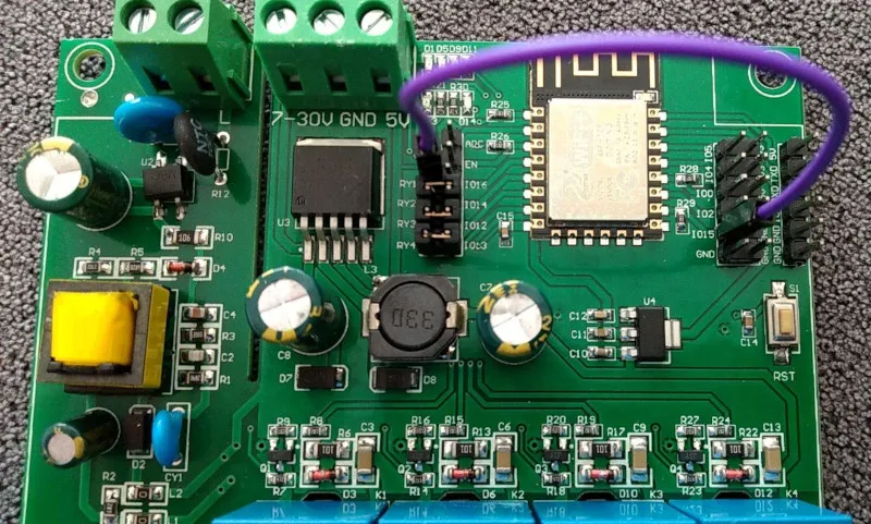
relaisboard.JPG (147.37 KiB) Viewed 719 times
https://www.diymore.cc/collections/tags ... ec5b&_ss=r

I was able to flash it with: mega-20240229 (leap-build) (Collection C) hoping to be able to revive it with Serial MCU controlled switch.

However using the plugin with LC TECH (if that would be correct) at 9600 19200 115200 there is nu music in the relais. Powered the board via 5v externally.

Any suggestions?
Last edited by sincze on 10 Mar 2024, 18:26, edited 2 times in total.

User avatar
Ath
Normal user
Posts: 3520
Joined: 10 Jun 2018, 12:06
Location: NL

Re: diymore AC/DC Power Supply ESP8266 WIFI Four-Way Relay Module ESP-12F Development Board

#2 Post by Ath » 10 Mar 2024, 16:31

Looking at the components on the board, I'd expect the relays to be controlled directly via GPIO pins of the ESP, and that will probably be GPIO-12, 13, 14 and 16.
You can test that from the Tools page, sending command gpio,12,1 or gpio,12,0 etc. to switch a relay.

The LC-Tech plugin is designed to send serial commands to a LC-Tech relay board, that's, AFAIK, not equipped with an ESP processor, so can't run ESPEasy directly.


NB: When adding power to the board, please use 5V or the 7-30V input, to avoid dangerously high voltages from the mains lines
/Ton (PayPal.me)

TD-er
Core team member
Posts: 8756
Joined: 01 Sep 2017, 22:13
Location: the Netherlands
Contact:

Re: diymore AC/DC Power Supply ESP8266 WIFI Four-Way Relay Module ESP-12F Development Board

#3 Post by TD-er » 10 Mar 2024, 16:35

The LC-tech plugin is intended to communicate with a separate microprocessor running its own firmware.
This board indeed doesn't seem to have such a co-processor so it looks like you might be able to just toggle some GPIO pin.

Just try to toggle GPIO pins and try not to use GPIO 6 - 11 as those are connected to flash.
See: https://espeasy.readthedocs.io/en/lates ... on-esp8266

sincze
Normal user
Posts: 43
Joined: 15 Jul 2016, 12:54

Re: diymore AC/DC Power Supply ESP8266 WIFI Four-Way Relay Module ESP-12F Development Board

#4 Post by sincze » 10 Mar 2024, 17:14

To be honest I started with the GPIO test before moving (reflashing) to Collection-C to try the LC_Tech idea.
relay-close.jpg
relay-close.jpg (163.8 KiB) Viewed 706 times
Through the command box I tried flipping from 0 to 1 and 1 to 0

Code: Select all

gpio,0,1
gpio,1,1
gpio,2,1 (Blue light switches on ESP)
gpio,3,1
gpio,4,1
gpio,5,1 (set to 0 this enables LED D1)
gpio,12,1
gpio,13,1
gpio,14,1
gpio,15,1
gpio,16,1
Relais are not clicking. Power is through YwRobot at 10v DC.
From the board I can tap 5v 3,3V DC from the pins on the right side.
Reset button resets the device. Any other ideas ?

User avatar
Ath
Normal user
Posts: 3520
Joined: 10 Jun 2018, 12:06
Location: NL

Re: diymore AC/DC Power Supply ESP8266 WIFI Four-Way Relay Module ESP-12F Development Board

#5 Post by Ath » 10 Mar 2024, 17:33

I've marked the 4 most likely pcb traces to control the relays.
You can use a multi-meter to track back to what GPIO pin they lead... (when the board is NOT powered on!)
Screenshot - 10-03-2024 , 17_29_46.png
Screenshot - 10-03-2024 , 17_29_46.png (663.29 KiB) Viewed 702 times
/Ton (PayPal.me)

sincze
Normal user
Posts: 43
Joined: 15 Jul 2016, 12:54

Re: diymore AC/DC Power Supply ESP8266 WIFI Four-Way Relay Module ESP-12F Development Board

#6 Post by sincze » 10 Mar 2024, 17:39

Ath wrote: 10 Mar 2024, 17:33 I've marked the 4 most likely pcb traces to control the relays.
You can use a multi-meter to track back to what GPIO pin they lead... (when the board is NOT powered on!)

Screenshot - 10-03-2024 , 17_29_46.png
Tnx. I like the notes that hint to blue smoke ;-) when the board is NOT powered on!)

I also found this similar piece of machinery:
https://templates.blakadder.com/ESP12F_Relay_X4.html

That would indicate you guys were right from the beginning.

Code: Select all

GPIO #	Component
GPIO00	User
GPIO01	User
GPIO02	Led_i 1
GPIO03	User
GPIO04	User
GPIO05	Led_i 2
GPIO09	User
GPIO10	User
GPIO12	Relay 3
GPIO13	Relay 4
GPIO14	Relay 2
GPIO15	User
GPIO16	Relay 1
GPIO17	User
Last edited by sincze on 10 Mar 2024, 17:46, edited 2 times in total.

TD-er
Core team member
Posts: 8756
Joined: 01 Sep 2017, 22:13
Location: the Netherlands
Contact:

Re: diymore AC/DC Power Supply ESP8266 WIFI Four-Way Relay Module ESP-12F Development Board

#7 Post by TD-er » 10 Mar 2024, 17:43

That template is for an ESP32, you have a board with ESP8266

sincze
Normal user
Posts: 43
Joined: 15 Jul 2016, 12:54

Re: diymore AC/DC Power Supply ESP8266 WIFI Four-Way Relay Module ESP-12F Development Board

#8 Post by sincze » 10 Mar 2024, 17:44

TD-er wrote: 10 Mar 2024, 17:43 That template is for an ESP32, you have a board with ESP8266
You beat me to it, i corrected myself ;-)

User avatar
chromo23
Normal user
Posts: 827
Joined: 10 Sep 2020, 16:02
Location: germany

Re: diymore AC/DC Power Supply ESP8266 WIFI Four-Way Relay Module ESP-12F Development Board

#9 Post by chromo23 » 10 Mar 2024, 17:50

Looking at the pcb it seems that j5 needs to be bridged with j6 since the the connections from the relays only lead to j5 (ry1 to ry4)

sincze
Normal user
Posts: 43
Joined: 15 Jul 2016, 12:54

Re: diymore AC/DC Power Supply ESP8266 WIFI Four-Way Relay Module ESP-12F Development Board

#10 Post by sincze » 10 Mar 2024, 18:09

chromo23 wrote: 10 Mar 2024, 17:50 Looking at the pcb it seems that j5 needs to be bridged with j6 since the the connections from the relays only lead to j5 (ry1 to ry4)
relay-close-fix.jpg
relay-close-fix.jpg (196 KiB) Viewed 683 times
Ding ding ding .

After noticing https://templates.blakadder.com/assets/ ... PIO15.webp
I bridged mine as well (no jumpers on my board... so jumper wires) probably need to solder some pins.
Then GPIO commands 12,13,14 work, for GPIO 16 another bridge is needed.

Strange delivery of hardware I must say.

TD-er
Core team member
Posts: 8756
Joined: 01 Sep 2017, 22:13
Location: the Netherlands
Contact:

Re: [SOLVED] diymore AC/DC Power Supply ESP8266 WIFI Four-Way Relay Module ESP-12F Development Board

#11 Post by TD-er » 10 Mar 2024, 21:29

As GPIO-16 is used, you probably can't use deepsleep on this board.

User avatar
ThomasB
Normal user
Posts: 1065
Joined: 17 Jun 2018, 20:41
Location: USA

Re: [SOLVED] diymore AC/DC Power Supply ESP8266 WIFI Four-Way Relay Module ESP-12F Development Board

#12 Post by ThomasB » 12 Mar 2024, 03:29

It's a nice touch that the relay's I/O assignments are not factory connected. You can freely choose the GPIO from header pads p3 (J6) and/or P4 (J7). That keeps it flexible.

- Thomas

sincze
Normal user
Posts: 43
Joined: 15 Jul 2016, 12:54

Re: [SOLVED] diymore AC/DC Power Supply ESP8266 WIFI Four-Way Relay Module ESP-12F Development Board

#13 Post by sincze » 12 Mar 2024, 08:36

ThomasB wrote: 12 Mar 2024, 03:29 It's a nice touch that the relay's I/O assignments are not factory connected. You can freely choose the GPIO from header pads p3 (J6) and/or P4 (J7). That keeps it flexible.

- Thomas
I agree on the flexibility part. Now I can use 2 relais and I2C sensors and a door sensor as well.

But they sell it as works with E-WLINK, but without these jumpers or pins I would not consider it "works with'. :D
Works With after modification that is.

Post Reply

Who is online

Users browsing this forum: No registered users and 42 guests