Page 1 of 1
Problems with ESPeasy and MAX31865
Posted: 23 Oct 2022, 12:40
by mdat
Hello,
I urgently depend on technical help. In nodeMCU with ESPeasy I pursue a MAX31865 with PT1000.
In ESPeasy SPI is activated. The values the ESPeasy is economical are fanciful, they go from 958 °C to-241 °C.
On every issue the value changes extremely.
NodeMCU as well as the MAX31865 and PT1000 I have exchanged quite several times without success.
I already have since several years other nodeMCU's with other measuring converters without problems run,
but now with MAX31865 I am to a point where I get further no more and hopes for your help.
Here are a few more Screenshots.
The best greetings
mdat
Re: Problems with ESPeasy and MAX31865
Posted: 23 Oct 2022, 13:11
by Ath
Have you tried using GPIO-15 (D8) instead of GPIO-4 (D4) for CS? As on many boards, GPIO-4 is connected to a Led, that might interfere with the SPI connection.
Re: Problems with ESPeasy and MAX31865
Posted: 23 Oct 2022, 13:15
by mdat
Yes, I had already tried D8, but without success.
Re: Problems with ESPeasy and MAX31865
Posted: 23 Oct 2022, 13:33
by Ath
And what build (name of the .bin file) of ESPEasy do you have installed?
Re: Problems with ESPeasy and MAX31865
Posted: 23 Oct 2022, 13:40
by mdat
ESP_Easy_mega_20220427_normal_ESP8266_4M1M
It is not the newest, but I fear in it it does not lie.
Re: Problems with ESPeasy and MAX31865
Posted: 23 Oct 2022, 14:01
by Ath
A newer release could help in some situations, but I don't expect that much has changed for ESP8266 regarding the SPI interface.
You have already triple-checked the connections & wiring between ESP and MAX31865, I assume, and that the wires aren't too long (< 30 cm would be good, shorter is better)?
Re: Problems with ESPeasy and MAX31865
Posted: 23 Oct 2022, 14:05
by mdat
Yes, I have also already done. I use to the test mostly pullover cable.
Re: Problems with ESPeasy and MAX31865
Posted: 23 Oct 2022, 17:23
by ThomasB
It might help to post several clear photos of what you have assembled. That way we can see if the MAX IC is a breakout board or bare chip. Plus we can review wiring lengths and other things.
- Thomas
Re: Problems with ESPeasy and MAX31865
Posted: 23 Oct 2022, 19:08
by mdat
Hello Thomas,
I have done sometimes a few pictures and if one hopes all important one can see on it.
Re: Problems with ESPeasy and MAX31865
Posted: 23 Oct 2022, 19:20
by Ath
A few remarks:
- Why is GND not connected on the MAX31865 board? (the blue wire seems to be connected to 3V3, but to GND on the NodeMcu?) Edit: Instead of to VIN, the 3V from NodeMcu should directly go to 3V3 on the MAX31865
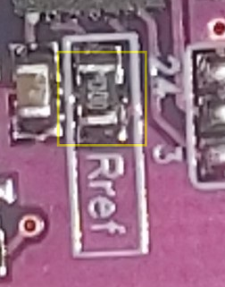
- The value of Rref should be entered in the ESPEasy settings, but I can't read/recognize the value from the photo
- Should some of the pads "2/3 Wire" and/or "2 Wire" be shorted, as you are using a 2-wire sensor?
Re: Problems with ESPeasy and MAX31865
Posted: 23 Oct 2022, 19:52
by ThomasB
Why is GND not connected on the MAX31865 board?
Yes, that is a big problem. Common Ground is needed.
Edit: Instead of to VIN, the 3V from NodeMcu should directly go to 3V3 on the MAX31865
Actually, the MAX breakout board has a 3.3V VREG on it. Normally its VIN should be connected to 5V and the 3.3V pin (VREG power out) is not used.
https://cdn-learn.adafruit.com/assets/a ... 1479237642
- Thomas
Re: Problems with ESPeasy and MAX31865
Posted: 23 Oct 2022, 19:53
by Ath
ThomasB wrote: ↑23 Oct 2022, 19:52
Actually, the MAX breakout board has a 3.3V VREG on it. Normally its VIN should be connected to 5V and the 3.3V pin should not be used.
Well, the NodeMcu doesn't have a visible 5V pin available, that's why I suggested to use the 3v3 directly

Re: Problems with ESPeasy and MAX31865
Posted: 23 Oct 2022, 19:56
by mdat
Hello Ath,
Excuse me, my mistake. With the GND has happened to me with the construction for the photo.
You surely have him was on 3.3 V. I had tried the red one also already on 3V3, with the same result.
Till present, however, I had even seen circuits with which the red on Vin was connected.
Rref is put on 4300 for PT1000.
Did the Pads like on the photo should were short-circuited?
Re: Problems with ESPeasy and MAX31865
Posted: 23 Oct 2022, 20:22
by ThomasB
The MISO pin on the NodeMCU will need a pullup resistor. Use 2.2K to 10K ohms, connect one end to MISO the other end to 3.3V.
Also, consult the schematic and board documentation for notes on configuring the breakout board's jumper pads.
- Thomas
Re: Problems with ESPeasy and MAX31865
Posted: 23 Oct 2022, 20:25
by Ath
mdat wrote: ↑23 Oct 2022, 19:56
Rref is put on 4300 for PT1000.
The value, present on the board, is to be entered in the configuration setting, and while I can't decipher it from the photo, it doesn't look like 4300 Ohm to me, maybe you can use a magnifying glass to have a better look
- Screenshot - 23-10-2022 , 20_18_26.png (183.92 KiB) Viewed 5811 times
mdat wrote: ↑23 Oct 2022, 19:56
Did the Pads like on the photo should were short-circuited?
Yes, that seems to be the intended connection. For production use, you could solder the pads on the board, they are intended for that

Re: Problems with ESPeasy and MAX31865
Posted: 23 Oct 2022, 20:33
by mdat
The right value stands on the board
Re: Problems with ESPeasy and MAX31865
Posted: 23 Oct 2022, 20:41
by Ath
According to this
SMD Resistor calculator the value is (most likely) 430 Ohm. To be sure you could try to measure using a digital multimeter, but only
after removing the power from the board.
But the difference would be results with a factor 10 off, I assume.
Edit: Having the 2/3 Wire and 2 Wire connections will probably give better results.
Re: Problems with ESPeasy and MAX31865
Posted: 23 Oct 2022, 21:00
by mdat
@Ath
The short circuit at the measuring places has brought nothing. As far as I know, 3 wires and 4 wire connections is to be measured only around the opposition value of the management out.
@Thomas I thought, actually, for this Boards if a pullup resistor was no more necessary there already the Rref 4300 is obstructed
Re: Problems with ESPeasy and MAX31865
Posted: 23 Oct 2022, 21:31
by mdat
Just also wear seen:
https://learn.adafruit.com/adafruit-max ... duino-code
My MAX31865 are for PT100 and not for PT1000.
I had bought them, actually, for PT1000.
Re: Problems with ESPeasy and MAX31865
Posted: 23 Oct 2022, 22:03
by Ath
That could explain the weird readings then, now to order the correct sensor or board.
Re: Problems with ESPeasy and MAX31865
Posted: 23 Oct 2022, 22:39
by mdat
I have somewhere one more PT100 and tomorrow will test it.
I already thank for your help
Re: Problems with ESPeasy and MAX31865
Posted: 24 Oct 2022, 03:01
by ThomasB
@Thomas I thought, actually, for this Boards if a pullup resistor was no more necessary there already the Rref 4300 is obstructed
I highly suggest a pullup resistor on the MISO D6 signal since this resistor is not present on the MAX breakout board. The Rref resistor is unrelated to the MISO signal, not the same thing.
- Thomas
Re: Problems with ESPeasy and MAX31865
Posted: 24 Oct 2022, 12:32
by mdat
Hello Ath,
I have it now after the instructions from: https: // learn.adafruit.com/adafruit-max31865-rtd-pt100-amplifier/rtd-wiring-config
done, and a PT100 uses and now everything functions.
Thanks for your help