
Ok, I have plugged the new S20 that he can use the 3rd AP. And the S20 see all!
Now there is really only one possible version left:
As long as the ESP's are connected to any AP, everything is fine. But if they are logged in at the box itself, the MESH master, then they no longer see each other.
In my opinion, the "here I am" data packet is forwarded via port 8266 via the MESH to all other APs, but not to the MESH master.
Conversely, however, this message is passed on to the APs by the devices registered on the MESH master.
The FritzBox as a MESH master is a one-way street for the data packets...
EDIT:
Just reboot the FritzBox and also all AP's and also all ESP's (in this order). Same as before...
So I'm running out of ideas. I will grab me a Malt and watch a film with my wife... ENough for today...
New (old) project...
Moderators: grovkillen, Stuntteam, TD-er
Re: New (old) project...
DLzG
Micha
Micha
Re: New (old) project...
I don't have any ESP connecting to the mesh master here as it is in a kinda 'unreachable' spot for WiFi devices...
So unless you're on the toilet, you won't likely connect to the WiFi on the modem.
So it is possible the AP on the modem itself won't forward the packets.
Not sure what kind of modem/router you have.
I have the 5530 fiber.
So unless you're on the toilet, you won't likely connect to the WiFi on the modem.
So it is possible the AP on the modem itself won't forward the packets.
Not sure what kind of modem/router you have.
I have the 5530 fiber.
Re: New (old) project...
7950AX on DSL
Firmware must be the same except the WAN- segment.
I will connect AVM with that problem... Let's see what they have to say about ...
EDIT:
Today I sent everything we could find out about this topic to AVM and opened a ticket. Let's see what they'll say about it.
Perhaps we should move all related messages to a new thread in this regard?
DLzG
Micha
Micha
Re: New (old) project...
Ok, back to the initial topic meanwhile ...
I just finished the PCB for one of my drawer projects. But while I was at toilet (while pooping always got my best/craziest ideas) a question come up that could at least kill this project.
So I ask...
Setup (like attachment):
Task 5: Communication - Serial Server, Software serial, RX GPIO13, TX none, 9600,8,n,2
Task 6: Communication - Serial Server, Software serial, RX GPIO14, TX none, 9600,8,n,2
Task 7: Communication - Serial Server, Software serial, RX GPIO15, TX none, 9600,8,n,2
Question 1:
What happens if e.g. data arrives at two inputs at the same time?
Because I cannot influence when the meter sends data; they come every 2 seconds as a push message...
Question 2:
I don't need a LAN2SER- receiver; send it to FHEM is all what I need. So it is enough to set the TCP-port to zero?
- Attachments
-
- Bild_2022-12-31_122511675.png (47.54 KiB) Viewed 4005 times
DLzG
Micha
Micha
Re: New (old) project...
Software serial will not work reliable at all when receiving data on several pins at once.
If you need this, either use those I2C to UART chips supported in ESPEasy, or use an ESP32 which has 3 hardware serial ports.
The ESP32 can re-assign almost any feature to almost pin.
If you need this, either use those I2C to UART chips supported in ESPEasy, or use an ESP32 which has 3 hardware serial ports.
The ESP32 can re-assign almost any feature to almost pin.
Re: New (old) project...
* Happy new year *
So much time has to be
Ok, thx for the info about. My gut feeling didn't deceive me...
Then I'll have a look at the I²C to UART thingy. I've got all the ESPs here so better use that as buy a 32 ... and I'm sure I'll fit a small chip more on the circuit board...
So much time has to be
Ok, thx for the info about. My gut feeling didn't deceive me...
Then I'll have a look at the I²C to UART thingy. I've got all the ESPs here so better use that as buy a 32 ... and I'm sure I'll fit a small chip more on the circuit board...
DLzG
Micha
Micha
Re: New (old) project...
ESP32 is likely less expensive and the Wemos D1 mini with ESP32 does have 2 rows of pins on each side, which should somewhat be the same pinout as the ESP8266 version of the Wemos D1 mini.
Those NXP I2C to UART chips aren't really cheap.
Those NXP I2C to UART chips aren't really cheap.
Re: New (old) project...
Yes, maybe a ESP32 is cheaper ... let me take look...
EDIT: Which I²C-to-UART do you mean? I can't find anything in the device list (or I'm still blind from Wiskey...)
BTW: If my choice fall on ESP32... like this one?
But that one with external antenna- connection is more my way I think:
I haven't think about the ESP32 before so is that both ok for my project? I think so...
EDIT2:
10 minutes ago I kicked my fuse while I switch on my analog power supply for my amateur radios. On that circuit also the FritzBox is present, since 2 weeks without a UPS (battery death). So the FritzBox have to go from a cold start but not the repeater (other fused circuit). After the FritzBox are back again.... the ESP's now see each other (for the moment). That I will investigate more! I have do a cold start often since the "I don't see you" problems are up but that haven't that effect before...
EDIT: Which I²C-to-UART do you mean? I can't find anything in the device list (or I'm still blind from Wiskey...)
BTW: If my choice fall on ESP32... like this one?
- Bild_2023-01-01_125209584.png (295.89 KiB) Viewed 3983 times
- Bild_2023-01-01_125530616.png (357.6 KiB) Viewed 3983 times
EDIT2:
10 minutes ago I kicked my fuse while I switch on my analog power supply for my amateur radios. On that circuit also the FritzBox is present, since 2 weeks without a UPS (battery death). So the FritzBox have to go from a cold start but not the repeater (other fused circuit). After the FritzBox are back again.... the ESP's now see each other (for the moment). That I will investigate more! I have do a cold start often since the "I don't see you" problems are up but that haven't that effect before...
DLzG
Micha
Micha
Re: New (old) project...
Are you making the boards yourself?
These ESP32 modules are a bit hard to solder, so when I make boards I let JLCPCB solder them for me (SMT service)
I always use the 16MB modules with IPEX connector for my own boards.
This way I am not limited to where to place the ESP as the antenna can be anywhere.
Like these: https://www.aliexpress.com/item/4000287 ... 1802yyhWbv
Please keep an eye on page about which pins to use on an ESP32.
Especially GPIO12 should not (!!!) be pulled to a specific state at boot as it might destroy the flash chip. (pin state at boot sets the flash voltage)
Also some pins are input-only.
Re: New (old) project...
Yes, I develop my PCB's by myself (KiCAD, Altium) but let produce it external due it's hard to make VIA's by myself (and also the PCB looks ugly)
With soldering that stuff I have absolutely no problem. I'm old but I'm able to handsolder 0402 without problems... In fakt to my eyes going older 0201 is an adventure meanwhile so that I don't use it anymore in my projects if possible. I also have a hot air rework station and (thanx to my former boss) an small IR heating plate.
The thing with the external antennas is exactly what I prefer and have in mind; we think similar in that. This is particularly important for this project, since the circuit board is located in a closed meter cabinet. There is no HF going in or out. In addition, you are much more flexible. I still have 3 or 4 small chip antennas (as on the 07) with IPEX connectors that the company used to have left over. They are very practical because you can plug them in directly without any cable fuss if you don't need a WiFi range (on the crafting table, for example).

EDIT:
What's the difference between WROOM-32U and WROOM-32UE. They both looks identical to me ...
With soldering that stuff I have absolutely no problem. I'm old but I'm able to handsolder 0402 without problems... In fakt to my eyes going older 0201 is an adventure meanwhile so that I don't use it anymore in my projects if possible. I also have a hot air rework station and (thanx to my former boss) an small IR heating plate.
The thing with the external antennas is exactly what I prefer and have in mind; we think similar in that. This is particularly important for this project, since the circuit board is located in a closed meter cabinet. There is no HF going in or out. In addition, you are much more flexible. I still have 3 or 4 small chip antennas (as on the 07) with IPEX connectors that the company used to have left over. They are very practical because you can plug them in directly without any cable fuss if you don't need a WiFi range (on the crafting table, for example).
Very good hint! I'm sure that I'm crash into that without your hintEspecially GPIO12 should not (!!!) be pulled to a specific state at boot as it might destroy the flash chip.
Do you have an inexpensive and reliable source of supply, preferably on eBay, where I can buy 10 pieces?I always use the 16MB modules with IPEX connector for my own boards.
EDIT:
What's the difference between WROOM-32U and WROOM-32UE. They both looks identical to me ...
DLzG
Micha
Micha
Re: New (old) project...
I always order them along with the PCB, so I order at JLCPCB and they use LCSC as they seem to be closely related.
If you have an option, better use rev.3 ESP32.
Those have some small fixes in them. The issues they fix do have work-arounds either in the SDK or in ESPEasy, so both will work.
But I do feel better when you use the hardware without those bugs
If you have an option, better use rev.3 ESP32.
Those have some small fixes in them. The issues they fix do have work-arounds either in the SDK or in ESPEasy, so both will work.
But I do feel better when you use the hardware without those bugs
Re: New (old) project...
... it isn't possible in most offers to catch the revision they sell ... That's the 1st problem...
The 2nd problem is that I can't register at aliexpress due they don't accept any eMail- address I have try with "enter a valid email" So aliexpress is out for me ...
Found a description that explains the difference between the versions:
ESP32-WROOM-32: Original variant, based on the ESP32-D0WDQ6 chip
ESP32-WROOM-32D: First revision, uses the ESP32-D0WD chip
ESP32-WROOM-32U: Like 32D, but with U.FL antenna connection
ESP32-WROOM-32E: New revision, uses the ESP32-D0WD-V3 chip
ESP32-WROOM-32UE: Like 32E, but with U.FL antenna connector
The 2nd problem is that I can't register at aliexpress due they don't accept any eMail- address I have try with "enter a valid email"
Found a description that explains the difference between the versions:
ESP32-WROOM-32: Original variant, based on the ESP32-D0WDQ6 chip
ESP32-WROOM-32D: First revision, uses the ESP32-D0WD chip
ESP32-WROOM-32U: Like 32D, but with U.FL antenna connection
ESP32-WROOM-32E: New revision, uses the ESP32-D0WD-V3 chip
ESP32-WROOM-32UE: Like 32E, but with U.FL antenna connector
DLzG
Micha
Micha
Re: New (old) project...
I strongly advice to also include the 2 transistors for toggling the RST and GPIO-0 which makes it a lot simpler to flash the unit.
Or if you don't have room for it, make sure to include pads to these pins for whatever you use to flash.
Or if you don't have room for it, make sure to include pads to these pins for whatever you use to flash.
Re: New (old) project...
What do you mean with that? Any schematics where I can take a look ?the 2 transistors for toggling the RST and GPIO-0
BTW: Find some at ali but can't order there due it's noch possible to enter my correct shipping address
The website programmers are the biggest jerks I've ever seen...
DLzG
Micha
Micha

Re: New (old) project...
You may need to allow java-script in your browser temporarily, for that site, to pass the check
/Ton (PayPal.me)
Re: New (old) project...
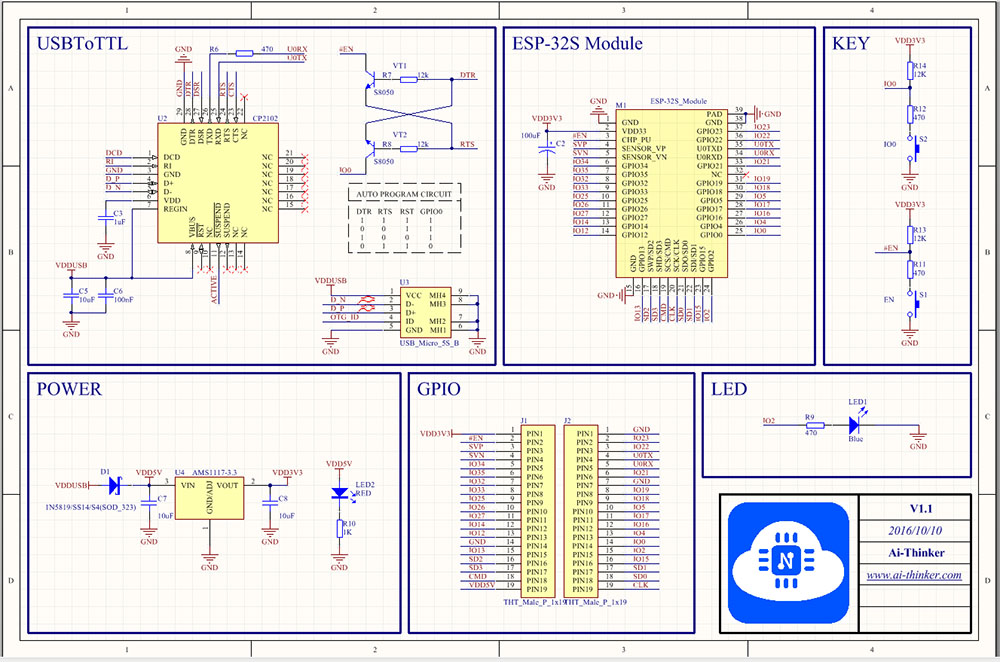
The 2 transistors (and resistors) in the top left corner.
This also shows the needed pull-up or -down resistors.
Re: New (old) project...
... that have nothing to do with java ...
You only can pic a given city/town. And if they don't exist you loose ...
If I set my postal code the only option is to chose "Niedersachsen/Celle"... But "Niedersachsen" isn't a city or town and Celle isn't match my postal code...
So simply no way ...
You only can pic a given city/town. And if they don't exist you loose ...
- Bild_2023-01-01_163522803.png (7.74 KiB) Viewed 3963 times
So simply no way ...
DLzG
Micha
Micha
Re: New (old) project...
Thanx for the SCH
I don't understand the meaning behind the transistor circuit (but how it works is clear). As usual, I have provided a reset button and a button for IO0. Because my small USB-UARTS have no DTR/RTS control lines
I don't understand the meaning behind the transistor circuit (but how it works is clear). As usual, I have provided a reset button and a button for IO0. Because my small USB-UARTS have no DTR/RTS control lines
DLzG
Micha
Micha
Re: New (old) project...
All ESP flash tools can toggle those DTR and RTS pins on an USB to UART controller in such a way that the RST and GPIO-0 are "pressed" to set the ESP in flash mode.
If you don't mind toggling those pins yourself, then you can ignore them.
If you don't mind toggling those pins yourself, then you can ignore them.
Re: New (old) project...
Ok, you mean one of the OnDesk- programmer like ...
That might work. But when the module is soldered on the new target board, I only have GND, TX, RX, VCC if I want to reflash the ESP in productive use directly at the meter. I don't usually go there, dismantle everything, unsolder the ESP and put it back on the DevBoard just because I want to do an update. And as I said before: the small USB-UARTS don't have RTS/CTS; I have only single USB-UART, a so-called All-In-One, that handles I²C, SPI, UART, MEM and EPP. It actually has RTS and CTS in UART mode, but that isn't that what I take with me while I'm on run with the notebook ...
- Bild_2023-01-01_174358818.png (111.8 KiB) Viewed 3948 times
DLzG
Micha
Micha
Re: New (old) project...
I often add a header compatible with these boards: https://www.aliexpress.com/item/3289284 ... 1802HM3YTu
This had the DTR/RTS pins available on them.
You may need to add a blob of solder at some pads on it to send the right pins (and voltage) to the 6p header, but then you can easily let the RST and Gpio-0 toggle by the flashing tool.
N.B. most of these boards are set to output 5V (and 5V levels) so you need to add a blob of solder on the back to set it to 3V3 and on the most recent boards you also need to scratch/cut 1 tiny trace between the center and "5V" pad.
Re: New (old) project...
Sure, but I know these are sold on a lot more sites
Re: New (old) project...
... that's maybe true ... Haven't find them yet at i.e. eBay... But I think that's the same like the ESP32... You can find one at Amazon for 30$ each out of the Espressif-Store. But at other places you get 10 pieces for the same price... I think same will come up with this little piece of tech
DLzG
Micha
Micha
Re: New (old) project...
And what about DealExtreme or Banggood?
Re: New (old) project...
... hmmm, never hear about them ... I take a look ...
Nope... nothing at both ...
DLzG
Micha
Micha
Re: New (old) project...
... you have see viewtopic.php?p=62136#p62136 with the explanation of the different versions.
If I understand correctly, the V1.0 shown here does not refer to the ESP, but only to the whole module, right?
If I understand correctly, the V1.0 shown here does not refer to the ESP, but only to the whole module, right?
- Bild_2023-01-02_000253039.png (230.29 KiB) Viewed 3912 times
DLzG
Micha
Micha
Re: New (old) project...
Given the date of "2018", I think it might be the older revisions of the silicon.
But as I mentioned, it is merely a preference, not a must to go for the v3.
Better focus on the "16M flash" which allow you to use the "max" builds so you don't have to make plugin selections as those have all.
But as I mentioned, it is merely a preference, not a must to go for the v3.
Better focus on the "16M flash" which allow you to use the "max" builds so you don't have to make plugin selections as those have all.
Re: New (old) project...
... I have do a little more research ...
It looks like that the year stamp just showing the revision- date of the PCB; same with the V1.0 on top/right. I find different PCB's , marked with V1.2, V2.0, V2.1, V2.2 or nothing and also other designed heat sink pad in the middle.
I also found a hint that say that the 3x3pad heat sink is the new one, the solid the old one.
But most of them are offered with ESP32-D0WD-V3 chip, no matter how the PCB is. So you have just take a look if the dealer say any about the used ESP and if not, you can be sure that an old ESP is build in...
Meanwhile I have ordered 10 pieces with 4M at Reichelt; they don't have the 16M. But Reichelt is one of my very long dealer I trust well. Better to have the 4M then nothing due the bullshit with "AliBrainLess - I'm too stupid to spill a bucket of water"
Digi-Key have the 16M but I don't pay 18,-€ for shipping
I grow my order to 15 pieces and then shipping is free. So I have ordered 15 with 16M
It looks like that the year stamp just showing the revision- date of the PCB; same with the V1.0 on top/right. I find different PCB's , marked with V1.2, V2.0, V2.1, V2.2 or nothing and also other designed heat sink pad in the middle.
I also found a hint that say that the 3x3pad heat sink is the new one, the solid the old one.
But most of them are offered with ESP32-D0WD-V3 chip, no matter how the PCB is. So you have just take a look if the dealer say any about the used ESP and if not, you can be sure that an old ESP is build in...
- Bild_2023-01-02_093212858.png (718.92 KiB) Viewed 3654 times
Meanwhile I have ordered 10 pieces with 4M at Reichelt; they don't have the 16M. But Reichelt is one of my very long dealer I trust well. Better to have the 4M then nothing due the bullshit with "AliBrainLess - I'm too stupid to spill a bucket of water"
Digi-Key have the 16M but I don't pay 18,-€ for shipping
I grow my order to 15 pieces and then shipping is free. So I have ordered 15 with 16M
DLzG
Micha
Micha
Re: New (old) project...
Ok, new problem
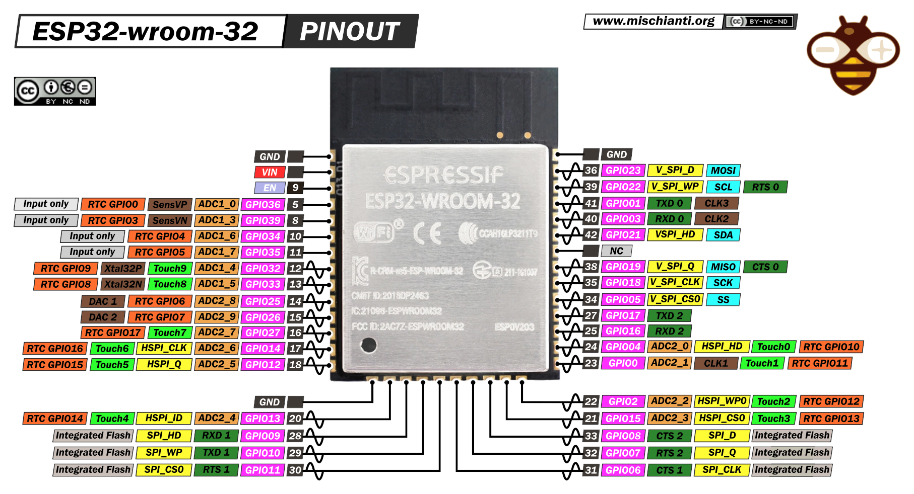
You say that the 32 have 3 UARTS so that I can use RX0, RX1 and RX2. So if I take a look at the data sheet RX1 (GPIO 9) is in use by the internal Flash (see also here: https://www.mischianti.org/wp-content/u ... lution.png)
So isn't that a problem?!
You say that the 32 have 3 UARTS so that I can use RX0, RX1 and RX2. So if I take a look at the data sheet RX1 (GPIO 9) is in use by the internal Flash (see also here: https://www.mischianti.org/wp-content/u ... lution.png)
So isn't that a problem?!
DLzG
Micha
Micha
Re: New (old) project...
on esp32 you can re-assign almost any feature to almost any pin.
you can use all 3 UARTs on almost any pin you like.
Just keep in mind not to pick used pins or pins with input-only as TX and keep in mind some pins may need a specific boot state.
That's all.
you can use all 3 UARTs on almost any pin you like.
Just keep in mind not to pick used pins or pins with input-only as TX and keep in mind some pins may need a specific boot state.
That's all.
Re: New (old) project...
ok, that's great... So if I only need inputs (I have nothing to send out, only to receive) I can also use i.e. GPIO 32 to 36and 39 (PIN 4 to 9) as RX0 to RX2 ?
DLzG
Micha
Micha
Re: New (old) project...
Not 100% sure what you mean...
But if it is about "input-only" pins as RX, then "yes".
Just keep in mind that if you like to use analog inputs, you should only use those connected to ADC1. ADC2 is used by WiFi, thus those analog input pins will not be useful when you use WiFi.
The higher numbered GPIO pins are connected to ADC1, so that's a trade-off you need to make.
Also there was something with pins 4 and/or 5 (which are default for I2C on ESP8266) like pull-up/down resistors, which makes them unfit for some use cases like I2C on ESP32.
So maybe this will also render them unfit for UART use? You may need to check "the table"
Re: New (old) project...
... ohhh men ... That's not as easy as I expected
Ok, you have understand me right...
Now I have chose IO 2, 12 and 14 (pin 13, 14 and 24) for serial data input.
They are declared as:
Will that be ok? 

I just need one more for PWM-out, best on the "left" side, any of the free pins 26 to 37. I just have chose pin 30 (IO18: V_SPI_CLK, SCK) ???
Ok, you have understand me right...
Now I have chose IO 2, 12 and 14 (pin 13, 14 and 24) for serial data input.
They are declared as:
Code: Select all
IO  2: ADC2_2, HSPI_WP0, Touch2, RTC IO12
IO 12: ADC2_5, HSPI_Q, Touch5, RTC IO15
IO 14: ADC2_6, HSPI_CLK, Touch6, RTC IO16I just need one more for PWM-out, best on the "left" side, any of the free pins 26 to 37. I just have chose pin 30 (IO18: V_SPI_CLK, SCK) ???
- Bild_2023-01-03_100539318.png (34.66 KiB) Viewed 3342 times
DLzG
Micha
Micha
Re: New (old) project...
GPIO-12 is a big red flag!
Problem with GPIO-12 is that it either has a pull-up or pull-down resistor based on the used flash chip as it sets the flash voltage at boot.
So you should never pull it to the other state at boot.
Best to not use this pin unless you really need to as you run out of pins.
GPIO-2 has an internal pull-down and is often connected to a LED when present on the boards.
Why not simply use GPIOs mentioned here without any yellow or red remarks? https://espeasy.readthedocs.io/en/lates ... e-on-esp32
Oh and maybe also add some 500 Ohm resistor in series with the RX/TX lines to prevent ringing?
Re: New (old) project...
Oh and make sure you have the original RX0/TX0 accessible as you may need to access them for flashing via serial.
When you re-map the pins for Serial0, it still is Serial0.
So make sure to disable "Enable Serial" on the tools->Advanced page to prevent sending logs to the Serial0 port.
When you re-map the pins for Serial0, it still is Serial0.
So make sure to disable "Enable Serial" on the tools->Advanced page to prevent sending logs to the Serial0 port.
Re: New (old) project...
Japp, ok... RTX0 is going to header J2 for flashing.
So if I understand right then if I "bend" only RX0 and not TX0 to IO2 (for now; I will change it) the original logdata stay at IO1 ?
... ahhh yes! Now I remember that you have tell me any about IO12 in the past... Have forget that
And now I have copy and print out the table you show me... Haven't seen that; don't ask why... I don't know...
And yes, some resistor in the TX/RX isn't a bad idea. Haven't never trouble without but but it certainly doesn't hurt
DLzG
Micha
Micha
Re: New (old) project...
There are 3 hardware serial ports on the ESP32.
Serial 0 ... Serial 2
You can re-assign almost any pin to them, but it still remains Serial0 ... Serial2
The logs are sent to Serial0 (when "Enable Serial" is checked on tools->Advanced page)
So you can re-route those signals to whatever pin you like, but it still may show data sent to Serial0.
In theory, you can also map multiple pins to the same signal in the GPIO-MUX on the ESP32, but that's not supported in ESPEasy.
But this pin-mux is a really great feature of the ESP32 and is why we can map almost any function to almost any pin.
I keep saying almost, since some features are for sure hard-wired to some pins. For example the analog input pins and also the signals needed for connecting Ethernet are fixed. But if you don't use Ethernet, those can be used freely for other features.
Re: New (old) project...
Ok, got it... I think.
So if I only bend RX0 to an other Port TX0 still stay on GPIO1 (J2 Pin3 in my schematic) and send LogData as before ?
To break things down a bit, what I actually want...
There are only two EasyMeters in my house. But a friend already has three of them in the meter cupboard and I think four or more meters are likely to be more common.
So I want to keep things as universal as possible. In the absence of UARTs, three counters are the end here. Therefore, it would also be worth considering equipping the slave board (J3) with its own UART...
Which UART chips are supported by ESPeasy?
DLzG
Micha
Micha
Re: New (old) project...
With "Enable Serial" checked, you also accept commands sent to the RX pin of Serial0
So this may still interfere as the received data from a sensor will then be parsed as if it is a command.
Let's call this "Enable Serial" checkbox "Enable Serial Console", to indicate what it does.
Some plugins may grab the data from it, before it is sent to the "console", but I don't know what this will do to sending the logs as you only can set 1 baud rate per serial port.
Re: New (old) project...
... ahhh ok ... Now I really get it. I have to see it as a coupled system for each UART and can't decouple RX and TX from one port as independent ... Right?!
DLzG
Micha
Micha
Re: New (old) project...
IO have not find any I²C to UART in the list at https://espeasy.readthedocs.io/en/lates ... lugin.html
https://www.maxlinear.com/product/inter ... /xr20m1280
Not easy to solder by hand but things like that I have in mind ...
https://www.nxp.com/products/peripheral ... 40_750_760
That's also an option... but the buffer size is very small... 64bit seems not enough... or am I wrong?
DLzG
Micha
Micha
Re: New (old) project...
The one which is supported right now is the NXP SC16IS752
This has indeed 64 bytes of buffer.
How big will your packets be and at what baudrate?
It can indeed be a bit tight, as I had recently adapted the PMSx003 plugin code to actually support this I2C to serial bridge to overcome these issues.
This is a rather 'chatty' device, so I had to adapt the plugin code a bit to make sure the serial buffer was read more efficiently.
Simply waiting for an entire packet to be present in the buffer before reading is not the right strategy when handling serial ports
However this is how lots of libraries tend to work, so there might be some plugins that need to be 'patched' to make it work with these bridges.
Re: New (old) project...
... that here is a sample packet that comes all 2 seconds as push-message with 9600,8,n,2
Code: Select all
/ESY5Q3DA2056 V3.01

1-0:0.0.0*255(1050000650)
1-0:1.8.0*255(00000000.4500000*kWh)
1-0:21.7.255*255(000030.00*W)
1-0:41.7.255*255(000250.00*W)
1-0:61.7.255*255(000070.00*W)
1-0:1.7.255*255(000350.00*W)
1-0:96.5.5*255(62)
0-0:96.1.255*255(1ESY1050000565)
!
DLzG
Micha
Micha
Re: New (old) project...
Looks like P1 meter data.
But the message you showed was already > 128 bytes, so it would also not fit entirely in the ESP's hardware serial buffers.
Meaning regardless of how the data will be received, you still need to read from these buffers several times a second to get a complete message.
But the message you showed was already > 128 bytes, so it would also not fit entirely in the ESP's hardware serial buffers.
Meaning regardless of how the data will be received, you still need to read from these buffers several times a second to get a complete message.
Re: New (old) project...
... yepp, that's the problem ...
Hmmm... Maybe a Atmel as buffer... Most have an hardware UART and more then enough memory. But who can code that?!
Or back to the 1st idea with an Raspberry Pi Zero W ....
Hmmm... Maybe a Atmel as buffer... Most have an hardware UART and more then enough memory. But who can code that?!
Or back to the 1st idea with an Raspberry Pi Zero W ....
DLzG
Micha
Micha
Re: New (old) project...
Why is this a problem?
The current P1 reader plugin also supports large messages.
It is just a matter of reading the buffer at least 15x a second for a 64 byte buffer @ 9600 baud.
Or at least 7.5x a second for 128 bytes buffer.
So it should be called in the PLUGIN_FIFTY_PER_SECOND call and you should be fine.
Don't think in limits to hold you back, but rather in artificial lines which are just a reminder to be creative
Re: New (old) project...
Or use ESPEasy plugin P044 P1 WiFi Gateway, that can be installed multiple times.
When using a build from PR #4283, where this plugin has been merged back into P020 Serial Server where it was originally copied from, with additional features, and when running on an ESP32, there should be enough memory available to read it into the plugin buffer (max 1024 bytes ATM) before passing it on to the next destination.
The plugin doesn't do any parsing of the data though (maybe I should add 'yet', as I'm still considering that as an option).
/Ton (PayPal.me)
Who is online
Users browsing this forum: Bing [Bot], Google [Bot] and 135 guests