Basics: The I²C Bus
 You may hear some construction noise in the background...
Contents
Introduction
I²C: Inter-Integrated Circuit, sometimes found as IIC, due to legal reasons sometimes called TWI (Two Wire Interface).
I²C was developed by Philips Semiconductors (Today named NXP) as a bus for the internal communication between parts of a device,
mainly a controller and it's peripherals. Originally it was used to control the electronics of TV sets and CD players
from a central controller board inside the box.
Many sensors and actors can be driven by I²C so we will explain some tech chinese here
to give some basic understanding.
Basic Circuitry
An I²C Bus consists of a master and one or more slaves.
These components are connected by four wires:
Vcc: The power supply. With ESPEasy this is 3,3V, or 5V if a level shifter is used.
GND: Ground.
SCL: Signal Clock, always provided by the master.
SDA: Signal Data.
With ESPEasy the signals use the pins
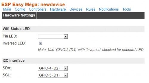
GPIO-4 (D2) = SDA
GPIO-5 (D1) = SCL
You may change these pins within the "hardware" tab in ESPEasy:
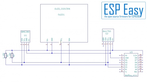
Let's have a look at a alldays use schematic for demonstration.
At the right side you see a WeMos D1 Mini, our ESP with ESPEasy firmware.
The WeMos is the master of the I²C bus.
Then you see three slaves: A BH1750 luminosity sensor, an OLED display and a
BME280 (Environment Sensor, temperature, pressure and humidity)
At the left you may notice two "pull up's", resistors.
Let's explain these resistors first.
The devices on the I²C-bus do not provide +Vcc on the data lines.
Why not?
They are simply connected together. If one device sends a "0", it
connects the data or clock line to ground. This would short circuit
the connection to +Vcc on the other devices!
If the I²C is idle, or sending a "1" it needs +Vcc. so we have to provide some Vcc to the wires. This is done by the resistors.
Some basic rules for placing and dimensioning:
- Resistors should be placed together at one end of the bus.
Avoid placing several resistor pairs.
- If you have short leads on a breadboard or a single PCB, two 10KOhn resistors are sufficient.
Often the internal pullups inside the ESP do the job in this case.
- If you want to connect some PCB's inside a box, lower the resistor value. In most cases 4,7KOhm works well.
- In case you have to expand the I²C longer (up to 1m), reduce the resistors to 2,2 KOhm.
Be aware that long I²C connections are somewhat delicate.
Do not use resistore below 2,2 KOhm! This might load too much current to the I2C devices.
Are longer connections then 1m possible?
Yes and no. Theoretically they are not. But it is possible to use so called "Line Drivers"
to expand the I²C connection. This is what TV sets do with long HDMI cables, they use I²C too.
This special case is not covered in this text.
Addressing
Every I²C device has an unique address. As they are all lined up on the same wires
this address is necessary for the master to differ who is sending data right now.
Think of it as a kind of electronic street number.
With some I²C devices it is possible to change the I²C address (note the not connected
"ADR" Pin on the BH1750 Sensor in the schematic). The OLED display may change address via
soldering bridges at the backside, some breakout boards use jumpers.
This is used if you want to place two devices of same type on the bus.
Important: Do NOT use two devices with same address. It will confuse the I²C.
How does it work?
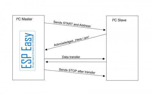
If the I²C bus does nothing ("idling"), both lines are "high", logical "1".
For starting a data transfer the I²C master sends a "START" command, followed by the address of the slave the master want's to access.
The addressed slave acknowledges with a signal saying "Here i am and i'm ready".
Now data are send from or to the master. As usual with serial data transfer the data is sent "bit by bit".
The clock signal gives the "next bit please" clock for this transfer.
At the end of the transfer the master sends a "stop" signal. This puts the I²C bus back into the idle state.
At this point you should understand why same address with two I²C slaves will not work:
The Master sends the address and two slaves put their "Acknowledge" on the I²C same time. The result simply is bit garbage.
Please note: This explanation is very simplified. We left out a lot of steps and things,
for example how the slave decides if the master want's to send or to receive data.
But for explaining to a non-techie's daily use it should suffice.
I²C devices with 5V
Do NOT connect I²C devices using 5V to the ESP directly! This kills the ESP.
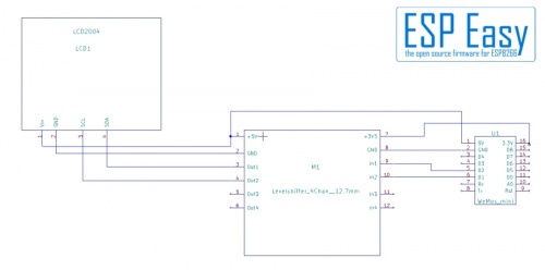
Here we can't work with a simpe voltage divider, we need a level shifter.
The level shifter transforms the 3,3V signals from the ESP into 5V signals for the I²C device, in this case an LCD2004 display.
No pull up resistors?
Most nowadays level shifter use FET transistors for transforming.
These need resistors anyways so they are already on the level shifter.
Get it to work
Before starting with I²C devices make sure your device is supported by ESPEasy at all!
All in all it needs no witchcraft to get I²C to work.
Check Adresses
Check the I²C addresses of your devices.
This is usually not a problem as long as you use different devices but it may lead into unexpected issues.
Just one example: You use a LCD2004 display and a PCF8574 GPIO extender.
Bad news: The I²C-Converter at the backsinde of the LCD uses a PCF 8574 too! Now you definitely have to check for addresses!
Another example: LCD2004 and PN532 RFID reader.
For some reasons it seems to run into problems if the "A0" address of the LCD is "1" (Soldering bridge on the I²C converter of the display is open).
If those two do not work together try closing the "A0" soldering points on the LCD converter.
Connect devices
Connect your devices. Enjoy a cup of coffee and then check all connections again.
So many issues are just caused by wrong or bad connections.
A best practice is connecting the I²C slaves one by one, not all together at same time.
Check the device
Start your ESP and open the webpage.
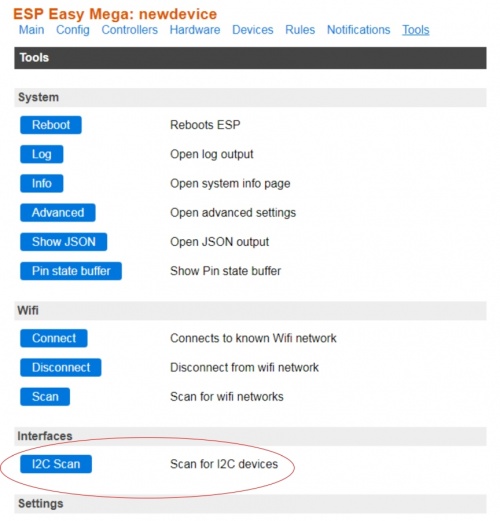
Go to the "Tools" tab and click "I2C Scan"
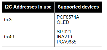
You should get an output like this:
Don't worry if you get a lot of devices shown. As long as your device shows up within the listet devices everything is OK.
Due to limitations with the I²C the scan shows a "Device found at address 0X..." but can't say which one so ESPEasy shows
a list of possibly connected devices.
Now you may configure the next slave device and repeat the check.
It should now show two occupied addresses and two device lists as shown in the picture above.
If all devices are connected you may start to configure them in the device tasks list.
Something went wrong? Troubleshooting
First I²C device not running
Bad news: You just connected the first device and it is not shown in the scan.
What to do now?
At first, check your cabling and connections.
The contacs of breadboards are well known for being unreliable. Cheap breadboard cables might look nice
but do they really have contact? Check them with an ohmmeter or multimeter.
Second: Check your settings!
By default the I²C lines are:
GPIO-4 (D2) = SDA
GPIO-5 (D1) = SCL
but are they in your ESP configuration and your cabling?
Often it helps to just swap the SCL and SDA wires or swap the pins in the "Hardware" tab.
Re-Check the "Hardware" settings of your ESPEasy. Still set to GPIO4 and 5?
If you're using a multi-channel level shifter, try to change to other channels. The FET's on this
tiny boards are somewhat sensitive and tend to get broken sometimes.
I²C stops when additional device is connected
Again: Check cabling and connections. One device with SDA and SCL swapped stops the whole I²C subsystem.
If possible check if the additional device runs alone, without other I²C devices connected.
Note the address and check if there are other devices at same address. If so, change the address of one of the devices.
Even if there are no address conflicts visible, try to change the address. Some devices seem to have problems with address decoding so it might help.
[To do: Text Formatting, Include Pictures]
