PCF8574
Introduction
The number of GPIO pins on the ESP module can be expanded with a IO Expander. We will use the PCF8574 that provides 8 more pins that can be used as input or output. This way it becomes possible to control an 8 channel relay board.
Each individual pin can be used as either input or output. It can also be helpful in improving system stability when using ESPEasy for actuators. It is an unfortunate reality that the ESP reboots randomly. This can be extremely annoying depending on your application. The PCF8574 keeps the GPIO states as the ESP reboots (as long as power is not disconnected).
Hardware


The PCF8574 needs to be connected through the I2C interface. This chip is compatible with 3V3 and therfore can be connected to the ESP without levelshifters.
Connections
See below example for ESP01. It can be connected to any two GPIOs capable of runnning I2C (GPIO 1&3 on a Sonoff for example)
 PCF8574 	ESP-01
 GND ( 8) 	GND
 VCC (16)   	VCC
 SDA (15)	GPIO 0
 SCL (14)	GPIO 2
When using the PCF8574 be aware of the extremely limited current the GPIO pins can source. If LED or Relays are to be driven (even just the transistors) , make sure to use the GPIO to sink the current --> connect device to 3.3V VCC and GPIO. Switch device on by setting the GPIO to Low. If necessary 2 GPIO can be tied together (must also always be switched together) to sink more current.
ESP Easy
Configuration depends on how you want to use a certain port on this device. Ports are numbered 1 to 8 (if you have a single PCF8574 connected)
Input
To have an input port act as an input switch device (just like with the default onboard GPIO pins) you need to edit a ESP Easy task and select the "PCF8574 input" device.
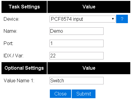

You then select the portnumber and additional configuration depending on the controller type. For Domoticz, you enter the IDX that was allocated by Domoticz for this virtual switch.
Portnumbering depends on the I2C address used:
For the PCF8574:
| A0: | A1: | A2: | Address: | Port range: |
|---|---|---|---|---|
| 0 | 0 | 0 | 0x20 | 1 - 8 |
| 1 | 0 | 0 | 0x21 | 9 - 16 |
| 0 | 1 | 0 | 0x22 | 17 - 24 |
| 1 | 1 | 0 | 0x23 | 25 - 32 |
| 0 | 0 | 1 | 0x24 | 33 - 40 |
| 1 | 0 | 1 | 0x25 | 41 - 48 |
| 0 | 1 | 1 | 0x26 | 49 - 56 |
| 1 | 1 | 1 | 0x27 | 57 - 64 |
For the PCF8574A:
| A0: | A1: | A2: | Address: | Port range: |
|---|---|---|---|---|
| 0 | 0 | 0 | 0x38 | 65 - 72 |
| 1 | 0 | 0 | 0x39 | 73 - 80 |
| 0 | 1 | 0 | 0x3A | 81 - 88 |
| 1 | 1 | 0 | 0x3B | 89 - 96 |
| 0 | 0 | 1 | 0x3C | 97 - 104 |
| 1 | 0 | 1 | 0x3D | 105 - 112 |
| 0 | 1 | 1 | 0x3E | 113 - 120 |
| 1 | 1 | 1 | 0x3F | 121 - 128 |
Commands
| Command | Value | Extra information |
|---|---|---|
| PCFGPIO,<pin>,<value> | 1,0 | Control PCF8574 output pins (1 or 0) |
| PCFPulse,<pin>,<value>,<duration> | 1,0 | Pulse control on PCF8574 output pins (duration in mS, MILLIseconds) |
| PCFLongPulse,<pin>,<value>,<duration> | 1,0 | Pulse control on PCF8574 output pins (duration in S, seconds) |