Tutorial Rules
Notice: This page is transitioning to a new format that includes updated Rules information for the latest ESPEasy Mega Releases. The revised Rules Tutorial can be found here: readthedocs
Contents
- 1 Introduction
- 2 Enable Rules
- 3 Syntax
- 4 Some working examples:
- 4.1 TaskValueSet
- 4.2 Event value (%eventvalue%)
- 4.3 PIR and LDR
- 4.4 SR04 and LDR
- 4.5 Timer
- 4.6 Starting/stopping repeating timers with events
- 4.7 HTTP call
- 4.8 SendTo and Publish
- 4.9 Time
- 4.10 SendToHTTP
- 4.11 Dew Point for temp/humidity sensors (BME280 for example)
- 4.12 Report IP every 30 seconds using MQTT
- 4.13 Custom reports to Domoticz with own IDX
- 4.14 One button, multiple actions using long press
Introduction
Along with ESP Easy R108, a new feature was enabled, named Rules. Rules can be used to create very simple flows to control devices on your ESP.
Enable Rules
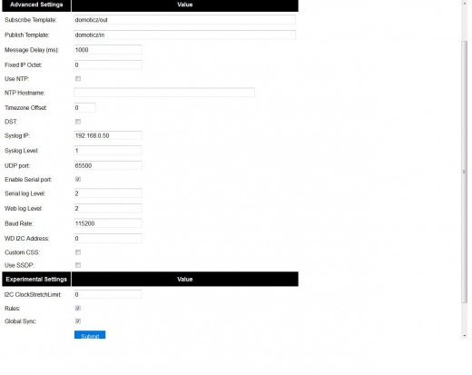
To enable rules, go to Tools/Advanced and check the Rules checkbox.
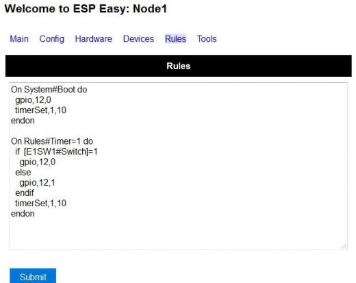
After clicking Submit, you will find a new page added. Here you can start experimenting with Rules:
The example above shows an experiment with a LED, connected via a resistor of 1k to GPIO12 and to ground.
A virtual switch needs to be created in the "Devices" section to allow the reading the state of the LED (on or off). The Device needs to be "Switch Input" with the following settings:
- Device Name - E1SW1
- Enabled - Ticked
- Internal PullUp - Ticked
- 1st GPIO - GPIO-12(D6)
- Switch Type - Switch
- Switch Button Type - Normal Switch
- Values Name change to "Switch"
After rebooting the ESP, the LED will start blinking 10 seconds on then 10 seconds off.
Alternatively the built in LED on many ESP8266 boards like the WEMOS D1 mini can be controlled using GPIO2.
Enjoy.
Syntax
The syntax of a rule can be single line:
on <trigger> do <action> endon
or multi-line (need to be closed with an "endon"):
on <trigger> do
<action>
<action>
<action>
endon
IF/ELSE
Also simple if ... else ... statements are possible:
on <trigger> do
 if <test>
   <action>
   <action>
 else
  <action>
 endif
endon
If the "else" part is not needed it can be removed:
on <trigger> do
 if <test>
   <action>
   <action>
 endif
endon
AND/OR
Only simple if/else was possible in older versions, there was this workaround for the limitation of not being able to nest. An "event" can be called from a "trigger". This possibilty of nesting events is also limited , due to its consumption of stack space (IRAM). Depending on plug-ins in use this might lead to unpredictiable, unreliable behaviour, advice is not to exceed 3 levels of nesting. link Forum discussion
on <trigger> do
 if <test1>
   event <EventName1>
 endif
endon
on <EventName1> do
 if <test2>
   <action>
 endif
endon
As of mega-201803.. we have the possibility to use AND/OR:
on test do
  if [test#a]=0 or [test#b]=0 or [test#c]=0
   event,ok
  else
   event,not_ok
  endif
endon
on test2 do
  if [test#a]=1 and [test#b]=1 and [test#c]=1
   event,ok
  else
   event,not_ok
  endif
endon
on test3 do
  if [test#a]=1 and [test#b]=1 or [test#c]=0
   event,ok
  else
   event,not_ok
  endif
endon
on test4 do
  if [test#a]=0
   event,ok
  else
   event,not_ok
  endif
endon
Up to two AND/OR can be used per if statement, that means that you can test three float values and if the statement is true/false corresponding action will take place.
Trigger
<trigger>
The trigger can be an device value being changed:
DeviceName#ValueName
Operator (inequality function)
Or a inequality function:
DeviceName#ValueName<inequality function><value>
Where the "inequality function" is a simple check:
equal (=) to
less (<) than
greater (>) than
less or equal (<=) to
greater or equal (>=) to
not equal (!= or <>) to
DeviceName#ValueName<<value>
DeviceName#ValueName=<value>
DeviceName#ValueName><value>
DeviceName#ValueName>=<value>
DeviceName#ValueName<=<value>
DeviceName#ValueName!=<value>
DeviceName#ValueName<><value>
(System) events
Some special cases are these system triggers which is triggered upon boot/reboot/time/sleep etc. of the unit:
| Event | Information | Example |
|---|---|---|
| <taskname>#<valuename> | As described already, each task can produced one or more events, one each for each measured value. You should not name your devices and value names so that the combination equals to any of the below listed system events! | on [DHT11Outside]#Temperature>20 do GPIO,2,1 endon |
| System#Wake | Triggered after power on | on System#Wake do GPIO,15,1 endon |
| System#Boot | Triggered at boot time | on System#Boot do GPIO,2,1 timerSet,1,30 endon |
| System#Sleep | Triggered just before the ESP goes to deep sleep | on System#Sleep do GPIO,2,0 endon |
| MQTT#Connected | Triggered when the ESP has connected to broker | on MQTT#Connected do Publish %sysname%/status,First message! endon |
| MQTT#Disconnected | Triggered when the ESP has disconnected from the broker | on MQTT#Disconnecteddo Reboot endon |
| MQTTimport#Connected | Triggered when the ESP has connected to broker (the MQTT Import plugin uses a separate connection than the generic one) | on MQTTimport#Connected Publish %sysname%/status,MQTT Import is now operational endon |
| MQTTimport#Disconnected | Triggered when the ESP has disconnected from the broker (the MQTT Import plugin uses a separate connection than the generic one) | on MQTTimport#Disconnecteddo Reboot endon |
| WiFi#Connected | Triggered when the ESP has connected to wifi | on WiFi#Connected do SendToHTTP url.com,80,/report.php?hash=123abc456&t=[temp2#out] endon |
| WiFi#ChangedAccesspoint | Triggered when the ESP has changed to access point, will also trigger first time the unit connects to the wifi | |
| Login#Failed | Triggered when (someone) has tried to login to a ESP unit with admin password enabled, but have failed to enter correct password | on Login#Failed do Publish %sysname%/warning,Intruder alert! endon |
| Time#Initialized | Triggered the first time (after boot) NTP is updating the unit | on Time#Initialized do Publish %sysname%/Time,%systime% endon |
| Time#Set | Triggered when the time is set by an update from NTP | on Time#Set do Publish %sysname%/Time,%systime% Publish %sysname%/NTP,Updated time at: %systime% endon |
| Clock#Time= | Triggered every minute with day and time like: Mon,12:30 or Tue,14:45. You can define triggers on specific days or all days using "All" for days indicator. You can also use wildcards in the time setting like All,**:00 to run every hour. | on Clock#Time=All,12:00 do //will run once a day at noon GPIO,2,1 endon on Clock#Time=All,**:30 do //will run half past every hour GPIO,2,1 endon On Clock#Time=All,%sunrise% do //will run at sunrise (%sunset% is also available) GPIO,2,1 endon |
| Rules#Timer= | As described already, triggered when a rules timer ends (setting a timer to "0" will disable the timer) | on Rules#Timer=1 do GPIO,2,1 endon |
Test
<test>
As described in the trigger section the test is a check done by checking if the DeviceName#ValueName is meeting a criteria:
[DeviceName#ValueName]<inequality function><value>
Where the value must be a float value with a dot as decimal sign. The DeviceName#ValueName is closed by (square) brackets "[" and "]".
Action
<action>
The action can be any system command found in the list of commands. Also plugin specific command are available as long as the plugin is in use. In the case mentioned earlier we use a action to trigger multiple logic tests (the "event" command).
Comment
If you want you can add comments to any row in your rules code. Just remember to add them after the code and always begin with "//":
on <trigger> do //If this happens then do that...
 if <test>
   <action>
   <action>
 else
  <action>
 endif //this is another comment
endon
Best practice
It is possible to use CAPITAL letters and lower case as you please but best practice is to use the same types of letters that are found in the command reference list, and plugin specific commands. For the logics (on, if, else ... ) the general idea is to use lower case.
Regarding spaces in names it is recommended to NOT use them as it makes bug testing rules a lot harder. Spaces between chunks of code is possible to make the code more readable:
[DeviceName#ValueName]<<value> //These work the same...
[DeviceName#ValueName] < <value>
Some working examples:
TaskValueSet
Dummy Device is a single way to store and read value on variable. Just create Generic - Dummy Device and variables inside it.
TaskValueSet TASKnr,VARnr,Value
This example for two switches that toggle one device (LED and Relay on GPIO 13 and 16).
on sw1#state do
  if [dummy#var1]=0
    TaskValueSet 12,1,0
  else
    TaskValueSet 12,1,1
  endif
  gpio,16,[dummy#var1]
  gpio,13,[dummy#var1]
endon

on sw1a#state do
  if [dummy#var1]=0
    TaskValueSet 12,1,1
  else
    TaskValueSet 12,1,0
  endif
  gpio,16,[dummy#var1]
  gpio,13,[dummy#var1]
endon
Event value (%eventvalue%)
Rules engine specific:
%eventvalue% - substitutes the event value (everything that comes after the '=' sign, only one value is possible)
Sample rules section:
 on remoteTimerControl do
   timerSet,1,%eventvalue%
 endon
Now send this command to the ESP:
http://<espeasyip>/control?cmd=event,remoteTimerControl=5
and it will set rules timer nr 1 to 5 seconds. Using this technique you can parse a value from an event to the rule engine.
Note that 'timerSet' is a rule command and cannot be run directly from a remote command.
If you want to check the transfered value within rules on the receiving ESP (condititon in if-statement), you will need to write the transfered value into a Dummy device using the TaskValueSet command. It is then possible to check the value of the Dummy device as condition in if-statement within rules.
PIR and LDR
 On PIR#Switch do
   if [LDR#Light]<500
     gpio,16,[PIR#Switch]
   endif
 endon
In other words: If the PIR switch is set (to either 1 or 0) and if the light value < 500, then set GPIO port 16 of the ESP.
 on PIR#Switch=1 do
   if [LDR#Light]<500
     gpio,16,[PIR#Switch]
   endif
 endon
Now the event is only triggered when the pir switches on.
SR04 and LDR
 on SR04#range<100 do
   if [ldr#lux]<500
     gpio,2,0
     gpio,16,1
   else
     gpio,2,1
     gpio,16,0
   endif
 endon
Timer
There are 8 timers (1-8) you can use:
 On System#Boot do    //When the ESP boots, do
   servo,1,12,0
   timerSet,1,10      //Set Timer 1 for the next event in 10 seconds
 endon
 On Rules#Timer=1 do  //When Timer1 expires, do
   servo,1,12,30
   timerSet,2,1       //Set Timer 2 for the next event in 1 second
 endon
 On Rules#Timer=2 do  //When Timer2 expires, do
   servo,1,12,0
   timerSet,1,30      //Set Timer1 for the next event in 30 seconds
 endon
Starting/stopping repeating timers with events
To disable an existing timer, set it to 0. This is useful to make repeating timers for things like alarms or warnings:
 //start the warning signal when we receive a start_warning event:
 On start_warning do
   timerSet,1,2
 endon

 //stop the warning signal when we receive a stop_warning event:
 On stop_warning do
   timerSet,1,0
 endon

 //create an actual warning signal, every time timer 1 expires:
 On Rules#Timer=1 do
   //repeat after 2 seconds
   timerSet,1,2

   //pulse some led on pin 4 shortly
   Pulse,4,1,100

   //produce a short 1000hz beep via a piezo element on pin 14
   tone,14,1000,100

 endon
To start or stop the warning signal use http:
 http://<espeasyip>/control?cmd=event,start_warning
 http://<espeasyip>/control?cmd=event,stop_warning
HTTP call
When you enter this first command with the correct IP address in the URL of your browser:
 http://<espeasyip>/control?cmd=event,startwatering
 http://<espeasyip>/control?cmd=event,stopwatering
And have this rule in the addressed ESP:
On startwatering do
  gpio,12,1 //start watering (open valve)
  timerSet,1,600 //timer 1 set for 10 minutes
endon

On stopwatering do
  timerSet,1,0 //timer 1 set to halt, used to stop watering before the timer ends!
  gpio,12,0 //stop watering (close valve)
endon

On Rules#Timer=1 do
   gpio,12,0 //stop watering (close valve)
endOn
Provided that you also have the valve etc, the plants will be happy.
SendTo and Publish
With SendTo you can add a Rule to your ESPEasy, capable of sending an event to another unit. This can be useful in cases where you want to take immediate action. There are two flavors: - SendTo to send remote unit control commands using the internal peer to peer UDP messaging - Publish to send remote commands to other ESP using MQTT broker
SendTo: SendTo <unit>,<command>
Imagine you have two ESPEasy modules, ESP#1 and ESP#2
In the Rules section of ESP#1 you have this:
 on demoEvent do
   sendTo 2,event,startwatering //(to use the previous example.)
 endon
And ESP#2 has the rules according to the previous example (givemesomewater)
If you then enter this with the correct IP address in the URL of your browser:
http://<ESP#1-ip >/control?cmd=event,demoEvent
Then ESP#1 shall send the event 'startwatering ' to ESP#2.
It is also possible to directly order gpio changes, like:
 on demoEvent do
   sendTo 2,GPIO,2,1
 endon
Publish
Publish <topic>,<value>
To be created.
Time
With Rules you can also start or stop actions on a given day and time, or even on every day.
 On Clock#Time=All,18:25 do // every day at 18:25 hours do ...
  gpio,14,0
 endon
Or for a specific day:
 On Clock#Time=Sun,18:25 do  // for Sunday, but All, Sun, Mon, Tue, Wed, Thu, Fri, Sat will do.
  gpio,14,0
 endon
It is also possible to use the system value %systime% in rules conditions to make things happen during certain hours of the day:
  On Pir#Switch=1 do
   If %systime% < 07:00:00
    Gpio,16,0
   Endif
   If %systime% > 19:00:00
    Gpio,16,1
   Endif
  Endon
This will set gpio 16 to 1 when the pir is triggered, if the time is before 7 in the morning or after 19:00 in the evening. ( useful if you don't have a light sensor)
SendToHTTP
To send a message to another device, like a command to switch on a light to Domoticz
On System#Boot do //When the ESP boots, do timerSet,1,10 //Set Timer 1 for the next event in 10 seconds endon On Rules#Timer=1 do //When Timer1 expires, do SendToHTTP 192.168.0.243,8080,/json.htm?type=command¶m=switchlight&idx=174&switchcmd=On endon
Many users have reported problems with commands being truncated, particularly when trying to send commands to domoticz. It seems to be a parsing error. There is the following workaround
SendToHTTP 192.168.0.243,8080,/json.htm?type=param=switchlight&command&idx=174&switchcmd=On
Dew Point for temp/humidity sensors (BME280 for example)
If you have a sensor that is monitoring the air temperature and the relative humidity you may calculate the dew point with rules. This example use MQTT to publish the values but you may change this to whatever you want. We also make use of a "dummy device" to dump values, this example use two BME280 with different i2c addresses. [How to change i2c address of BME280]
Set up BME280 devices as follows:

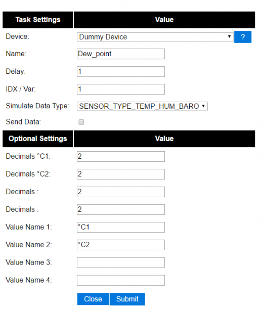
Set up dummy device as follows:


For dew point on the outside:
 on TempHumidityPressure_OUTSIDE#%RH do
  TaskValueSet,7,1,[TempHumidityPressure_OUTSIDE#°C]-(100-[TempHumidityPressure_OUTSIDE#%RH])/5  // "7" is the number of the task that the dummy device is on, "1" is its first value where we dump our result
  if [TempHumidityPressure_OUTSIDE#%RH]>49
   Publish %sysname%/DewPoint_OUTSIDE/°C,[Dew_point#°C1]
  else
   Publish %sysname%/DewPoint_OUTSIDE/°C,[Dew_point#°C1]*  //This asterix shows that the calculation is not correct due to the humidity being below 50%!
  endif
 endon
For dew point on the inside:
 on TempHumidityPressure_INSIDE#%RH do
  TaskValueSet,7,2,[TempHumidityPressure_INSIDE#°C]-(100-[TempHumidityPressure_INSIDE#%RH])/5  // "7" is the number of the task that the dummy device is on, "2" is its second value where we dump our result
  if [TempHumidityPressure_INSIDE#%RH]>49
   Publish %sysname%/DewPoint_INSIDE/°C,[Dew_point#°C2]
  else
   Publish %sysname%/DewPoint_INSIDE/°C,[Dew_point#°C2]*  //This asterix shows that the calculation is not correct due to the humidity being below 50%!
  endif
 endon
[More info about the simplified dew point calculation is found here.]
Report IP every 30 seconds using MQTT
This rule also work as a ping or heart beat of the unit. If it has not published a IP number for 30+ seconds the unit is experiencing problems.
On System#Boot do    //When the ESP boots, do
 Publish %sysname%/IP,%ip%
  timerSet,1,30      //Set Timer 1 for the next event in 30 seconds
endon

On Rules#Timer=1 do  //When Timer1 expires, do
 Publish %sysname%/IP,%ip%
  timerSet,1,30       //Resets the Timer 1 for another 30 seconds
endon
Custom reports to Domoticz with own IDX
This rule was presented as a workaround for a problem where a sensor had three different values but only one IDX value. You could publish your own Domoticz messages (MQTT or HTTP) using this method. Below we use the INA219 plugin that have 3 values which of the two second ones are Amps and Watts, just as an example we want to publish these as custom messages with a unique IDX value.
MQTT
on INA219#Amps do
  Publish domoticz/in,{"idx":123456,"nvalue":0,"svalue":"[INA219#Amps]"} //Own made up IDX 123456
endon

on INA219#Watts do
  Publish domoticz/in,{"idx":654321,"nvalue":0,"svalue":"[INA219#Watts]"} //Own made up IDX 654321
endon
HTTP
on INA219#Amps do SendToHTTP 192.168.1.2,8080,/json.htm?type=command¶m=udevice&idx=123456&nvalue=0&svalue=[INA219#Amps] //Own made up IDX 123456 endon on INA219#Watts do SendToHTTP 192.168.1.2,8080,/json.htm?type=command¶m=udevice&idx=654321&nvalue=0&svalue=[INA219#Watts] //Own made up IDX 654321 endon
(Given that your Domoticz server is on "192.168.1.2:8080", you should change to your server IP and PORT number. If the HTTP publishing is not working, please refer to this topic for a workaround.)
One button, multiple actions using long press
Using a "normal switch" device which is in this example normally set to low (0) you can make one of two actions when pressed. If you either release the button in less than a second or press it for more than a second:
on Button#State=1 do
  timerSet,1,1
endon

on rules#timer=1 do
 if [Button#State]=0
  //Action if button is short pressed
 else
  //Action if button is still pressed
 endif
endon

