Difference between revisions of "ESPEasy"
Grovkillen (talk | contribs) |
Grovkillen (talk | contribs) |
||
| Line 384: | Line 384: | ||
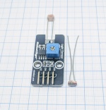
| [[File:Photosensitive_resistor.jpg|thumb|upright=0.5|center|link=Photosensitive resistor|[[Photosensitive resistor | Photosensitive resistor]]]] | | [[File:Photosensitive_resistor.jpg|thumb|upright=0.5|center|link=Photosensitive resistor|[[Photosensitive resistor | Photosensitive resistor]]]] | ||
| Light intensity<br/>Analog 1-100% or Binary above/below trigger value | | Light intensity<br/>Analog 1-100% or Binary above/below trigger value | ||
| − | | 3.3V- 5V | + | | 3.3V - 5V |
| 1 analog<br/>and/or<br/>1 digital | | 1 analog<br/>and/or<br/>1 digital | ||
| analog (0-3.3V)<br/>and/or<br/>binary (0/1) | | analog (0-3.3V)<br/>and/or<br/>binary (0/1) | ||
Revision as of 20:40, 25 May 2017
Contents
- 1 Introduction
- 2 Get started
- 3 Supported Hardware
- 4 Supported Sensors/Actuators
- 5 OLD Supported Sensors/Actuators List
- 6 Modded Hardware Products
- 7 Tutorials
- 8 Hardware Tips 'n Tricks
- 9 Examples
- 10 Loading firmware
- 11 Protocol selection
- 12 Configuration
- 13 ESP Easy web interface
- 14 Command Reference
- 15 System variables Reference
- 16 Tutorial Rules
- 17 Support and discussion
Introduction
The ESP Easy firmware can be used to turn the ESP module into an easy multifunction sensor device for Home Automation solutions like Domoticz. Configuration of the ESP Easy is entirely web based, so once you've got the firmware loaded, you don't need any other tool besides a common web browser.
The ESP Easy firmware is currently at build R120 an looks stable enough for production purposes as long as it's being used as a sensor device.
ESP Easy also offers limited "low level" actuator functions but due to system instability, this could be less useful in real life applications.
Get started
Getting started with the ESP Easy takes a few basic steps. In most cases your ESP module comes with the AT firmware or the NodeMCU LUA firmware. We need to replace the existing firmware with the ESP Easy firmware. We provide a (Windows only) flashtool to make this process an easy job.
1. Download firmware as binary including flash tool
↓
2. Connect the ESP to Windows PC
Using either USB/UART of board or separate USB/TTL adapter
↓
3. Write firmware using flash tool
Note necessity for GPIO to be LOW to enter flashmode
↓
4. Restart ESP. WiFi "AP ESP_0" will appear
↓
5. Search for you routers WiFi and connect
↓
6. Reconnect to your WiFi and enter IP adress sshown on previous screen
Supported Hardware
ESP Easy can be installed/flashed on nearly every piece of Hardware that has an ESP8266 built-in, newest 2.0.0 version even does support the ESP8285 (basically an ESP8266 with buildtin 1M Flash):
This is a (not yet complete) list of Hardware which is known to be supported:
| Device Name | ESP Chip | Flash Size | USB-TTL | GPIOs available | GPIO connected to onboard Hardware | onboard PSU/voltage regulator | Input voltage | Antenna | Size (LxWxH) |
|---|---|---|---|---|---|---|---|---|---|
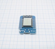
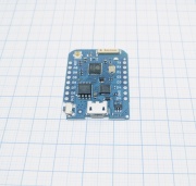
| 12 E/F | 4MB | CH340 | 0, 1, 2, 3, 4, 5, 12, 13, 14, 15, 16, A0 (with Voltage divider) | 1&3 (serial) | RT9013 | 5 VDC (+/-0,5V) | onboard PCB | 34.2mm x 25.6mm x ?mm | |
| 12 E/F | 16MB | CP2104 | 0, 1, 2, 3, 4, 5, 12, 13, 14, 15, 16, A0 (with Voltage divider) | 1&3 (serial) | RT9013 | 5 VDC (+/-0,5V) | onboard ceramic/pigtail connector | 34.2mm x 25.6mm x ?mm | |
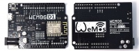
| WeMos D1 R2
|
12 E/F | 4MB | CP340G | 0, 1, 2, 3, 4, 5, 12, 13, 14, 15, 16, A0 (with Voltage divider) | 1&3 (serial) | 9-24VDC Switching power supply to 5 VDC(@1A) and RT9013 | 9-24VDC (power jack), 5VDC (5V pin) | onboard PCB | 68.6mm x 53.4mm x ?mm (=Arduino UNO) |
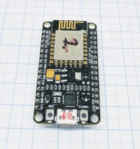
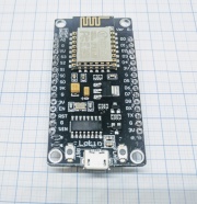
| NodeMcu V2
|
12 E | 4MB | CP2102 | 0, 1, 2, 3, 4, 5, 12, 13, 14, 15, 16, A0 (with Voltage divider) | 1&3 (serial) | ? | 5 VDC (+/-0,5V) | onboard PCB | ?mm x ?mm x ?mm |
| 12 E | 4MB | CP340 | 0, 1, 2, 3, 4, 5, 12, 13, 14, 15, 16, A0 (with Voltage divider) | 1&3 (serial) | ? | 5 VDC (+/-0,5V) | onboard PCB | ?mm x ?mm x ?mm | |
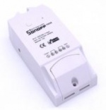
| generic ESP8266 | 1MB | None | 1, 3, (14) | 0 (button), 12 (Relay 10A@230VAC), 13 (LED) | on board mains AC to 5DVC + ? 3.3V Voltage Regulator Attention! The DC power is NOT galvanically decoupled from AC power! |
90-250VAC | onboard PCB | 88mm x 38mm x 23mm | |
| Sonoff TH10/TH16
|
generic ESP8266 | 1MB | None | 1, 3, (14) | 0 (button), 12 (Relay 10A/16A@230VAC), 13 (LED), 14 (AM2301) | on board mains AC to 5DVC + ? 3.3V Voltage Regulator Attention! The DC power is NOT galvanically decoupled from AC power! |
90-250VAC | onboard PCB | 88mm x 38mm x 23mm |
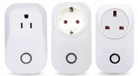
| Sonoff S20
|
generic ESP8266 | 1MB | None | 1, 3, (14) | 0 (button), 12 (Relay 10A@230VAC), 13 (LED) | on board mains AC to 5DVC + ? 3.3V Voltage Regulator | 90-250VAC | onboard PCB | ? |
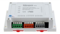
| Sonoff 4ch
|
generic ESP8285 | 1MB | None | 2, (7, 8) | 0, 9, 10, 14 (Buttons), 4 , 5, 12, 15 (Relay 10A@230VAC), 13 (LED blue) | on board mains AC to 5DVC buck converter + 3.3V Voltage Regulator | 90-250VAC | onboard PCB | 145mm x 90mm x 41mm |
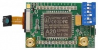
| Ai-Thinker A20 Breakout
|
generic ESP8285 | 1MB | None | ? | ? | ? | ? | SMA Connector | ? |

Supported Sensors/Actuators
| Device Type | Device Name | Physical values measured | Power requirements | connection method | output format | possible I²C addresses | level shifter required | mounting options | Size (LxWxH) |
|---|---|---|---|---|---|---|---|---|---|
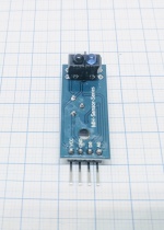
| PulseCounter | IR emitter + phototransistor (for ex. water/electricity meters), distance | 3.3V - 5V | 1 digital GPIO (for pulse/proxy) and/or 1 Analog input (distance) | binary(0/1) (for pulse/proxy)/ 0-3.3V (distance) | N/A | no | Ø? (1x or 2x) C-C? |
||
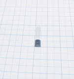
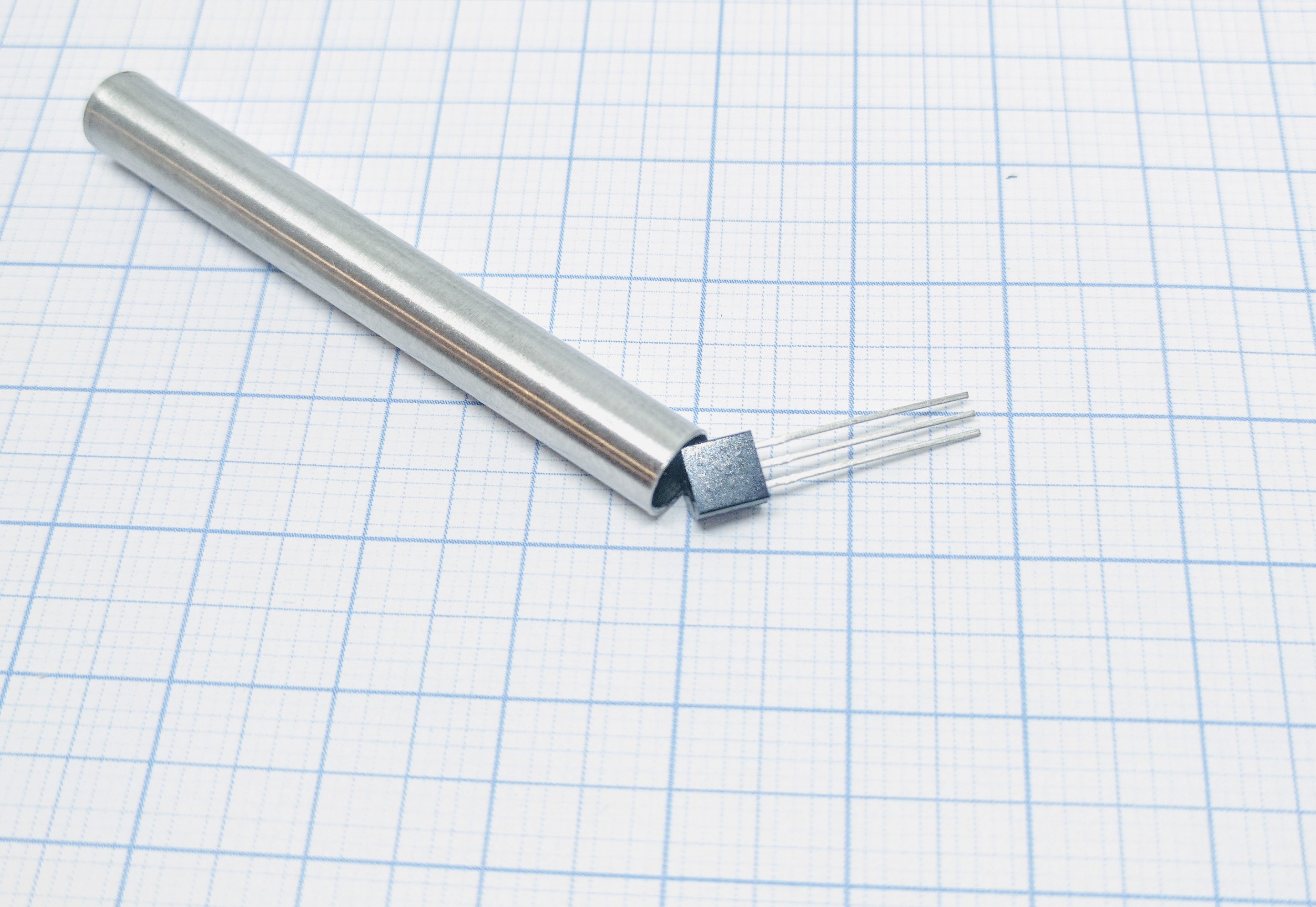
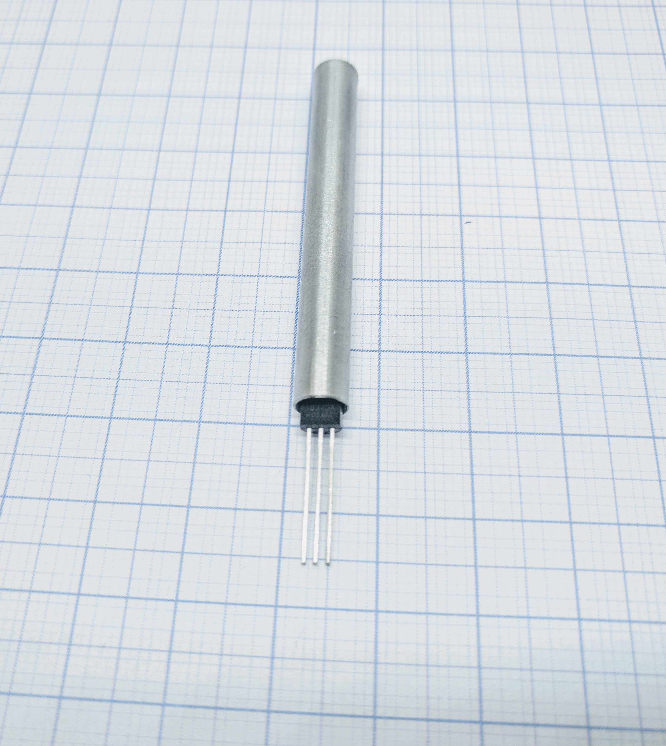
| Temperature Sensor | Temperature (-55 to +125°C) | 3.3V - 5V | 1 digital GPIO for multiple sensors | 1wire bus | N/A | no (yes if you use 5V logic and the ESP unit can't handle that voltage on GPIO) |
None but could be placed in a metal "pipe"/protective sleeve | Ø4.6mm x L4.6mm | |
| Temperature Sensor | Sensor temperature (-40 to +125°C)
IR temperature (-70 to +380°C) |
3.3V - 5V | SDA/SCL or 2 digital GPIO | I²C bus | 0x5a | no | Ø? (2x) C-C? |
||
| Environment | BMP085/BMP180 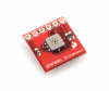
|
temperature (-40 to +85°C)
barometric pressure (300-1100 hPa) |
3.3V | SDA/SCL or 2 digital GPIO | I²C bus | 0x77 | no | Pins (6x) C-C2.54mm |
|
| Environment | BME280 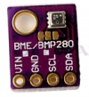
|
temperature (-40 to +85°C)
humidity ( 0…100 % rel. humidity) barometric pressure (300-1100 hPa) |
3.3V | SDA/SCL or 2 digital GPIO | I²C bus | 0x76 0x77 |
no | Ø? (1x) | 19.0mm x 18.0mm x 3.0mm |
| Environment | BMP280 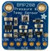
|
temperature (-40 to +85°C)
barometric pressure (300-1100 hPa) |
3.3V | SDA/SCL or 2 digital GPIO | I²C bus | 0x76 | no | Ø? (2x) C-C? |
19.0mm x 18.0mm x 3.0mm |
| Environment | MS5611 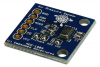
|
temperature (-40 to +85°C)
barometric pressure (10 to 1200 mbar) |
3.3V | SDA/SCL or 2 digital GPIO | I²C bus | 0x76 | no | Ø? (2x) C-C? |
19.0mm x 18.0mm x 3.0mm |
| PulseCounter | LJ12A3 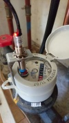
|
Inductive proximity sensor | 5V - 12V | 1 digital GPIO (for pulse/proxy) | binary(0/1) (for pulse/proxy) | N/A | no (yes if you consider pull-up and pull-down resistors as level shifter?) |
M12 thread | Ø12mm x L55mm |
| PulseCounter | Pulse logic input 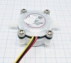
|
General, output as pulse | 5V - 12V (in general) | 1 digital GPIO (for pulse) | binary(0/1) (for pulse) | N/A | no | ||
| Gas Sensor | GP2Y10 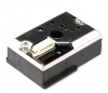
|
"Dust" (particle matter: PM2.5) | 5V | 1 analog (data) and 1 digital GPIO (for LED) | analog (for data) | N/A | no | Small flanges on the sides | 46.0mm x 30.0mm x 17.6mm |
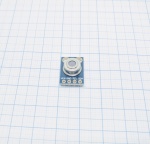
| Current | Current (max ±3.2A), Voltage (max. 26V) | 3.3V - 5 V | SDA/SCL or 2 digital GPIO | I²C bus | 0x40 0x41 0x44 0x45 |
no | Ø? holes (4x) C-C?? C-C?? |
? | |
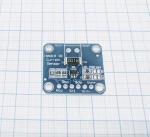
| Soil moisture | Soil moisture sensor 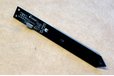
|
capacitive moisture, temperature, light | 3.3V - 5 V | SDA/SCL or 2 digital GPIO | I²C bus | 0x20 (changeable) | no | ? | ? |
| Gas Sensor | MH-Z19 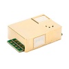
|
CO2 ppm, temperature, U | 3.3V | 2 digital GPIO (Software-Serial) | serial | N/A | no | Pins (4x + 5x) C-C2.54mm |
? |
| Light/Lux | BH1750 
|
Illuminance, Lux | 3.3V | SDA/SCL | I²C bus | 0x5c 0x23 |
no | Ø? holes (2x) C-C?? |
? |
| Light/Lux | TSL2561 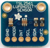
|
Illuminance, Lux | 3.3V | SDA/SCL | I²C bus | 0x29 0x39 0x49 |
no | Ø? holes (2x) C-C?? |
? |
| Light/Lux | TCS34725 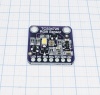
|
RGB Color | 3.3V | SDA/SCL | I²C bus | 0x29 | no | Ø? holes (2x) C-C?? |
? |
| Light/Lux | Light intensity Analog 1-100% or Binary above/below trigger value |
3.3V - 5V | 1 analog and/or 1 digital |
analog (0-3.3V) and/or binary (0/1) |
N/A | no | Ø? hole | ? | |
| Environment | temperature (-40 to +85°C)
humidity ( 0…100 % rel. humidity) |
3.3V - 5V | 1 digital GPIO for multiple sensors | 1wire bus | N/A | no | Ø? hole (DHT22) | ? | |
| Environment | DHT12 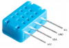
|
temperature (-20 to +60°C)
humidity ( 20…95 % rel. humidity) |
3.3V - 5V | 1 digital GPIO for multiple sensors | I²C bus (or 1wire bus) |
0xb8 | no | no | 12.3mm x 7.5mm x 4.7mm |
| Environment | SI7021/HTU21D 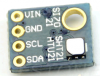
|
temperature (-40 to +125°C)
humidity ( 0…100 % rel. humidity) |
3.3V | SDA/SCL or 2 digital GPIO | I²C bus | 0x40 | no | ||
| Environment | SHT1X 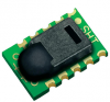
|
temperature
humidity |
3.3V - 5V | ? | ? | ? | no | ||
| Environment | AM2320 
|
temperature (-40 to +80°C)
humidity ( 0…99.9 % rel. humidity) |
3.3V - 5V | SDA/SCL or 2 digital GPIO | I²C bus | 0x5C (not found via i2c scan?) | no | ||
| RFID | Wiegand 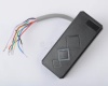
|
RFID | 6V - 12V | 2 digital GPIO | yes | ||||
| RFID | PN532 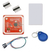
|
RFID | 3.3V | ? | no |
OLD Supported Sensors/Actuators List
| Sensors (Input) | |
|---|---|
| Distance | Switch |
HC-SR04 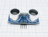 |
Switch  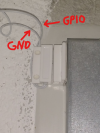 
|
| Analog | More Analog |
| Analog |
PCF8591  ADS1115 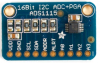
|
| Digital inputs | Infrared Receivers |
MCP23017  PCF8574 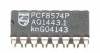 |
IR 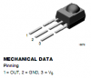
|
| Motion | |
MPU 6050 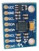
| |
| Actuators (Output) | |
|---|---|
| Digital output | Servo |
Output pin 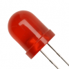 Relays |
Servo 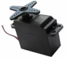
|
| IR-Transmit | Extra IO |
IR Led 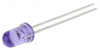 |
MCP23017 PCF8574
|
| PWM | Motor Shield |
PCA9685 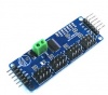 PWM GPIO 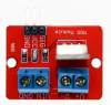 |
Adafruit Motor Shield v2 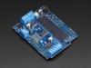
|
| Buzzer (RTTL) | |
RTTL 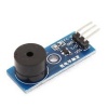
| |
| Other | ||
|---|---|---|
| LCD | OLED | Level Shifter |
| LCD Display |
OLED Display  |
Level Shifter |
Modded Hardware Products
| Device Type | Device Name | Recommended ESP8266 board | Information |
|---|---|---|---|
| Weather Station | Ventus W266 
|
WeMos D1 mini | This device is also sold as "RenkForce W205GU". |
Tutorials
- Using the flashtool to upload the ESP Easy firmware
- Using the Arduino IDE to upload the ESP Easy firmware
- Using the ESP Easy as a simple input switch in Domoticz
- Using the ESP Easy to control a LED of Relay from OpenHAB
- Rules, a modest way to locally control something in ESP Easy
- GlobalSync
Hardware Tips 'n Tricks
Examples
Loading firmware
- Current stable: ESPEasy R120
- Old release candidate: ESPEasy R147_RC8 (is being replaced by version 2.0)
- New release candidates are on github: ESPEasy version 2.0 and higher
Tutorial_ESPEasy_Firmware_Upload
Protocol selection
The ESP Easy supports several Home Automation controllers or web-services that collect sensor data.
Configuration
This section tells you more about the ESPeasy setup and the ESP unit's need to know settings (GPIO boot states etc.).
GPIO on ESP8266
| GPIO Number | GPIO Name | Boot State | Precautions and information |
|---|---|---|---|
| 0 | D3 | HIGH for boot LOW for serial programming |
Pullup resistor on most boards |
| 1 | Used as serial (TX) May be used but observe that signal might flicker due to serial activity during boot. | ||
| 2 | D4 | HIGH for boot HIGH for serial programming |
Connected to onboard LED (low active) Used as serial1 (TX1) |
| 3 | Used as serial (RX) May be used but observe that signal might flicker due to serial activity during boot. | ||
| 4 | D2 | Generally used as SDA (I2C) | |
| 5 | D1 | Generally used as SCL (I2C) | |
| 6 | Do not use! Reserved for SPI + flash | ||
| 7 | Do not use! Reserved for SPI + flash | ||
| 8 | Do not use! Reserved for SPI + flash | ||
| 9 | D11 | Do not use! Reserved for SPI + flash | |
| 10 | D12 | Use with caution! Reserved for SPI + flash | |
| 11 | Do not use! Reserved for SPI + flash | ||
| 12 | D6 | ||
| 13 | D7 | ||
| 14 | D5 | ||
| 15 | D8 | LOW for boot | Pulldown resistor on most boards |
| 16 | D0 | No PWM. No internal pullup available. Used in sleep mode for wakeup |
ESP Easy web interface
The ESP Easy has a user-friendly web interface for all configuration settings. They are locally stored in flash memory and retained on power-off. We will explain all configuration pages and settings:
Main page
URL:<espeasyip>

This is an informational page that provides some technical and operational parameters. The bottom half shows a node list of all known ESP units that are running in your network (this is optional and needs to be configured in tools/advanced) The list only shows live systems.
Config page
URL:<espeasyip>/config
Main settings can be found under "Config" page.

Name Can be set to an easy to remember name for this system. Can also be used in MQTT communication templates.
Admin Password Can be set if you want to protect your system config with a password.
SSID Wifi network SSID
WPA Key The key used on your Wifi Access Point
WPA AP Mode Key The key that ESP Easy will use if it starts as a Wifi Access Point to set the first time configuration
Unit nr Each ESP Easy unit needs a unique number in the range 1-31. This is important for MQTT connections and the Node list! Do not forget to set this field to a non-zero value, not conflicting with other units.
Protocol Select the protocol for your Home Automation controller or webservice like ThingSpeak.
Locate Controller You can set the controller based on it's DNS hostname or it's IP address.
Controller IP/Hostname Set IP or hostname for the controller
Controller Port Set the TCP port used on your controller or webservice.
Sensor Delay Set the delay between sensor reporting in seconds.
Sleep Mode Tick this field to use the ESP in deepsleep mode for low power operation. Read more: SleepMode
Optional
ESP IP You can set a static IP for this ESP unit. Set to 0.0.0.0 to use DHCP
ESP GW If using a static IP, enter the gateway (not needed if no connection to internet is needed!)
ESP Subnet Enter the local used subnet, usually 255.255.255.0
ESP DNS Enter you local DNS server IP address. Usually the IP of your local internet router.
Controllers page (version 2.0+)
URL:<espeasyip>/controllers

It is possible to have multiple controllers/brokers activated.
Hardware page
URL:<espeasyip>/hardware

Status LED (version 2.0 only) Select the data pin used for a low active LED to show the status of the firmware. Use D4 (GPIO2) for the on-board blue LED.

SDA Select the data pin used for I2C communications.
SCL Select the clock pin used for I2C communications.
Pin mode x Select an optional boot state for this pin, either output low or high
I2C is a well known standard to let multiple devices communicate over just two wires (and ground). We use it to connect sensors to ESP Easy. You can connect multiple sensors to the same two wires. Don't forget to use pull-up resistors on both SDA and SCL, unless one of your sensors already has them mounted on board.
Rules page
URL:<espeasyip>/rules
 Here's where the rules goes.
Notifications page (version 2.0+)
URL:<espeasyip>/notifications

It is possible to have the ESP unit send emails or giving you notifications using a buzzer.
Devices page
URL:<espeasyip>/devices

This is a list of tasks that the ESP Easy will perform. A sensor needs to be defined here to get the values send to your controller.
After selecting a new device, press the ? button to get specific help on this device!
Most common mistake if your values remain 0: The ESP Easy mainly targets Domoticz and the internal framework is entirely build upon the IDX field. This needs to match Domoticz. If you run a different protocol, it can be any value but must be non-zero. Just choose '1' in those cases...
Tools page
URL:<espeasyip>/tools

Some maintenance tools.
Tools Log page
URL:<espeasyip>/log

This page can be used for debugging issues. The debug level is set to '2' by default and will show sensor readings. Debugging levels can be changed under Tools/Advanced.
If your system runs fine, you can set the level to '0' to turn of logging. This will save valuable RAM!
Tools Advanced page
URL:<espeasyip>/advanced

Subscribe Template Used for MQTT subscription. Selecting a MQTT protocol will automatically fill this field
Publish Template Used for MQTT publishing. Selecting a MQTT protocol will automatically fill this field It is also used for the Generic HTTP protocol. Create your custom template here.
MQTT Retain Msg
Message Delay To prevent overloading your controller or webservice, a delay between reports can be set. Defaults to 1000 milliseconds. For ThingSpeak, you need to set this to 15000! to have multiple sensor readings working
Fixed IP Octet Special network config where the ESP starts with DHCP to get the basic network config and then sets the last octet to a fixed IP.
Use NTP To enable internal software clock, synchronized using internet time.
NTP Hostname Can be left empty as it defaults to pool.ntp.org. Can be changed here if needed.
Timezone Offset Offset in minutes to GMT. In the Netherlands this should be '60'
DST Daylight Saving Time. Must be set manually when DST is active to adjust the time.
Syslog IP Enter your syslog server IP if you have one running and want to debug something.
Syslog level Level of log messaging to the syslog server. Can be set between 0 - 4 (0=no logging, 1=error, 2=error+info, 3=error+info+debug, 4=error+info+more debug)
UDP port This is used for communication between ESP unit's. 65500 is just a sample. Use a number that does not conflict with other systems on your network as the ESP uses broadcast messages. If you have a syslog server running, do not enter 514 here!. This fields needs to be non-zero to have the node list running.
Enable Serial Port Enable/disable the serial port.
Serial log level Level of log messaging to the serial port. Can be set between 0 - 4 (0=no logging, 1=error, 2=error+info, 3=error+info+debug, 4=error+info+more debug)
Web log level Level of log messaging to the web gui. Can be set between 0 - 4 (0=no logging, 1=error, 2=error+info, 3=error+info+debug, 4=error+info+more debug)
Baud Rate Serial port baud rate
WD I2C Address I2C address to send watchdog messages to. Experimental feature to feed a ATTiny based external watchdog.
Custom CSS Tick this box to use a custom CSS (style sheet). You must first upload a "esp.css" file one to use this. The CSS filesize can not exceed 4 kbyte!.
Use SSDP SSDP is a network protocol based on the Internet Protocol Suite for advertisement and discovery of network services and presence information. This option toggles this service.
Rules Tick this checkbox to enable the Rules section for scripting the device. Else the rules aren't visible and editable and won't be processed at all.
I2C ClockStrechLimit
Global Sync
Tools Wifi scan
URL:<espeasyip>/wifiscanner

Here's a list of all accessible wifi networks and their signal strength.
Tools I2C scan
URL:<espeasyip>/i2cscanner

If one or more I2C devices are connected to the ESP Easy, you can use this scan feature to verify if devices can be located using their I2C address. If no device is shown, you likely made a mistake on wiring or the I2C configuration in the Hardware page.
If the I2C scanner lists an address, it will also list some well known devices that are fixed or typically found on that address. It does NOT mean that the detected device is verified to work in any way. I2C devices use a 7 bit address and the ESP will just scan all 127 possible addresses. If a device listens to some address it will acknowledge this to the ESP. It does not report the type of device so the ESP can only tell that something is listening!
Tools Settings up/download
URL:<espeasyip>/upload (for uploading settings)

URL:<espeasyip>/download (for downloading settings, not a webpage but a direct download)

The ESP Easy settings can be saved to your computer so you can restore them if they are lost or you just want to restore them after some experimenting. You can also upload a custom style sheet.
The system recognizes only two filenames:
config.txt
This file contains the ESP main configuration settings, except security data. The filesize should be 32k. You can exchange this file with other people if you like, because WPA keys and config password are not stored into this file.
Security data cannot be saved or restored from file!
esp.css (Custom Style Sheet, max 4 kb !)
If you want to customize the web gui you can upload (a small) css file. Remember that the webgui is only there for configuration so customization is limited. You may use the following stylesheet as an working example or template for further customization. And don't forget to activate the uploaded stylesheet in the TOOLS>ADVANCED section by enabling the "Custom CSS" option.
* {
	font-family: verdana,sans-serif;
	font-size: 13px;
}
h1 {
	color: black;
	font-size: 16pt;
}

h1::after {
	content: " (Powersocket Livingroom)";  /* Give your Device an additional selfexplaing name after the topmost headline */
}

h6 {
	color: black;
	font-size: 10pt;
	text-align: center;
}
.button-menu {
	background: #3498db;
	background-image: -webkit-linear-gradient(top, #3498db, #2980b9);
	background-image: -moz-linear-gradient(top, #3498db, #2980b9);
	background-image: -ms-linear-gradient(top, #3498db, #2980b9);
	background-image: -o-linear-gradient(top, #3498db, #2980b9);
	background-image: linear-gradient(to bottom, #3498db, #2980b9);
	-webkit-border-radius: 7;
	-moz-border-radius: 7;
	border-radius: 7px;
	color: #ffffff;
	padding: 3px 10px 3px 10px;
	border: solid #1f628d 1px;
	text-decoration: none;
	margin:0px 2px;
}

.button-menu:hover {
	background: #8fd4ff;
	background-image: -webkit-linear-gradient(top, #8fd4ff, #3498db);
	background-image: -moz-linear-gradient(top, #8fd4ff, #3498db);
	background-image: -ms-linear-gradient(top, #8fd4ff, #3498db);
	background-image: -o-linear-gradient(top, #8fd4ff, #3498db);
	background-image: linear-gradient(to bottom, #8fd4ff, #3498db);
	text-decoration: none;
	margin:0px 2px;
}

.button-link {
	border: 1px solid;
	border-radius: 5px;
	background:ButtonFace;
	color:ButtonText;
	border-color:ButtonHighlight ButtonShadow ButtonShadow ButtonHighlight;
	padding: 5px 15px;
	text-decoration: none;
}
.button-link:hover {
	background-color:Highlight;
	color:HighlightText;
}
.button-link:active {
	border-color:ButtonShadow ButtonHighlight ButtonHighlight ButtonShadow;
}
th {
	background-color: #369;
	color: #ffffff;
	padding: 10px;
}
td {
	padding: 7px;
}
table {
	color: black;
	border-collapse:collapse;
}
.div_l {
	float: left;
}
.div_r {
	background-color: #080;
	border-radius: 7px;
	color: white;
	float: right;
	margin: 2px;
	padding: 1px 10px;
}
.div_br {
	clear: both;
}
Tools Firmware update using OTA
URL:<espeasyip>/update

Once your first ESP Easy firmware is loaded using the serial interface, subsequent updates can be loaded using the Wifi connection (if your unit has 1MB flash or more!). More details on OTA firmware update: EasyOTA
Tools File List (version 2.0+)
URL:<espeasyip>/filelist

Access to the ESP's files. Possible to download for backup, or upload your own files.
Tools SD CARD File List (version 2.0+)
URL:<espeasyip>/SDfilelist

Access to the ESP's files stored on the SD card (if any SD card). Possible to download for backup, or upload your own files.
URL:<espeasyip>/json

If you want to get the ESP units variables in a JSON package this is where you want to go. The page is not accessible through any webpage button like the other pages.
Command Reference
System variables Reference
Tutorial Rules
Most information on rules (=local logic on ESP without controller) can be found in the tutorial
Support and discussion
- Forum
- IRC: #espeasy @freenode
Source code development
Sources are on Github
Want to contribute? Anyone is invited to do so, but please read this first: ESPEasyDevelopmentGuidelines
If you're new to this, follow these guides:
- Install Atom and platformio: Tutorial Install Platformio
- If you want to be send us back your changes via github follow: Tutorial preparing to work with github (otherwise skip it)
- Then you're ready for: Tutorial building and uploading with platformio
- And eventually, if you did the github stuff: Tutorial Contributing Back To ESPEasy