Difference between revisions of "TSense (K70)"
Grovkillen (talk | contribs) |
Grovkillen (talk | contribs) m (→Hardware) |
||
| (27 intermediate revisions by the same user not shown) | |||
| Line 1: | Line 1: | ||
= Introduction = | = Introduction = | ||
| − | Using the plugin '''P052 | + | Using the plugin '''P052 Senseair''' you can use the tSense (K70) as a sensor for temperature, humidity and carbon dioxide. You can even use it to monitor the status of the internal relay, or control the relay as well. If you have the EFA version of the tSense the temperature adjustment is also possible to monitor. |
= Hardware = | = Hardware = | ||
| Line 9: | Line 9: | ||
[[File:TSense_018.jpg|300px]] | [[File:TSense_018.jpg|300px]] | ||
| − | The EFA model of tSense generally displays the temperature and carbon dioxide level. Other than that you have a software button for controlling the internal relay (on and off). It even have a 9 step slider used to control the indoor temperature (monitoring the status of this slider is | + | The EFA model of tSense generally displays the temperature and carbon dioxide level. Other than that you have a software button for controlling the internal relay (on and off). It even have a 9 step slider used to control the indoor temperature (monitoring the status of this slider is possible using the plugin). |
[[File:TSense_017.jpg|300px]] | [[File:TSense_017.jpg|300px]] | ||
| Line 47: | Line 47: | ||
[[File:TSense_010.jpg|300px]] | [[File:TSense_010.jpg|300px]] | ||
| − | To monitor the relay you need to take the ground - gray - from 7th via (from the top) and either connect it as in the picture below (which gives the relay a normal open mode) or to the first via (which gives the relay a normal closed mode). The yellow cable is connected to the communication side of the relay and then connected to the ESPs D6 (GPIO-12). | + | To '''monitor''' the relay you need to take the ground - gray - from 7th via (from the top) and either connect it as in the picture below (which gives the relay a normal open mode) or to the first via (which gives the relay a normal closed mode). The yellow cable is connected to the communication side of the relay and then connected to the ESPs D6 (GPIO-12). As of later versions of the plugin you can also trigger the relay using these commands ('''http://<espeasyip>/control?cmd=senseair_setrelay,<value>''', also work within rules and from MQTT messages): |
| + | |||
| + | {| class="wikitable sortable" | ||
| + | |- | ||
| + | ! Command | ||
| + | ! Value | ||
| + | ! Extra information | ||
| + | |- | ||
| + | |||
| + | | rowspan="3"|senseair_setrelay,<value> | ||
| + | | '''1''' | ||
| + | | Trigger the relay ON | ||
| + | |- | ||
| + | |||
| + | | '''0''' | ||
| + | | Trigger the relay OFF | ||
| + | |- | ||
| + | |||
| + | | '''-1''' | ||
| + | | Current plugin take over the control of the internal tSense control of the relay, setting the senseair_setrelay=-1 will reset this. | ||
| + | |- | ||
| + | |} | ||
| + | |||
| + | If you use ESP Easy to control the relay you can skip the soldering of the yellow and gray cables but it is not a problem if you have them (you get a double feedback that the relay is active/inactive). | ||
[[File:TSense_011.jpg|300px]] | [[File:TSense_011.jpg|300px]] | ||
| Line 65: | Line 88: | ||
[[File:TSense_016.jpg|300px]] | [[File:TSense_016.jpg|300px]] | ||
| − | DONE! Power up using the tSense's 24VDC/24VAC power adaptor and setup the ESP Easy according to the next section. | + | DONE! Power up using the tSense's 24VDC/24VAC (the unit is possible to function with input power 9VDC - 24VDC with no problem) power adaptor and setup the ESP Easy according to the next section. |
= ESP Easy = | = ESP Easy = | ||
| − | Setting up the tSense unit with the ESP Easy firmware is pretty straight forward. '''P052 | + | Setting up the tSense unit with the ESP Easy firmware is pretty straight forward. '''P052 Senseair''' is the name of the device plugin and you set it up as follows. |
'''Temperature''' | '''Temperature''' | ||
| Line 88: | Line 111: | ||
---- | ---- | ||
| − | ''' | + | '''Temperature Adjustment''' |
| + | |||
| + | [[File:TSense_ESP_Easy_TEMPERATURE_ADJUSTMENT.png|400px]] | ||
| + | |||
| + | ---- | ||
| + | |||
| + | '''Switch monitor status of relay''' is using the standard plugin for a switch (P001 Switch input). | ||
[[File:TSense_ESP_Easy_RELAY.JPG|400px]] | [[File:TSense_ESP_Easy_RELAY.JPG|400px]] | ||
| − | <span style="color: red>Please observe that you cannot CONTROL the relay, only monitor its status.</span> | + | <span style="color: red>Please observe that you cannot CONTROL the relay using this method, only monitor its status.</span> To control the relay you need the latest plugin and use '''senseair_setrelay''' command. |
== Indicators (recommended settings) == | == Indicators (recommended settings) == | ||
| Line 105: | Line 134: | ||
|- | |- | ||
| − | | Status | + | | Error Status |
| − | | ''' | + | | '''Error''' |
| − | | | + | | '''15''' |
| − | | | + | | '''0''' |
| − | | | + | | Used to present errors (if any):<br/>"-1" No error<br/>"0" No ability to communicate with CO2 sensor module.<br/>"1" CO2 measurement error.<br/>"2" Temp measurement error.<br/>"3" No ability to communicate with RH/T sensor module.<br/>"4" RH measurement error<br/>"5" Temp measurement error, sensor will use CO2 sensor temperature if RH/T temperature is unavailable. S_Temp will be set to NTC_Temp.<br/>"6" (not used)<br/>"7" (not used)<br/>"8" Error in output configuration. Output is still updated, i.e. can be 0-10V.<br/>"9" One or several bytes of sensors parameter memory (settings) are corrupt. |
|- | |- | ||
| Line 131: | Line 160: | ||
| '''0''' | | '''0''' | ||
| | | | ||
| + | |- | ||
| + | |||
| + | | Temperature Adjustment | ||
| + | | '''Level''' | ||
| + | | '''1''' | ||
| + | | '''0''' | ||
| + | | This raw value goes from 0 - 1000 in 9 steps.<br/>To have them displayed as -4 to 4 use this formula:<br/>'''%value%*0.008-4'''<br/>To have them displayed as 1 to 9 use this formula:<br/>'''%value%*0.008+1''' | ||
| + | |- | ||
| + | |||
| + | | Relay Status | ||
| + | | '''Relay''' | ||
| + | | '''1''' | ||
| + | | '''0''' | ||
| + | | This indicator monitor the software relay status, whereas the yellow/gray wiring monitor the hardware relay status (it's actual output). Both methods are good, just different. The software way of monitoring the status might be up to 1 second longer (if delay is 1 sec) due to the fact that a switch status is send instant compared to the relay status indicator which is sent once every X seconds. | ||
|- | |- | ||
|} | |} | ||
Latest revision as of 08:48, 23 July 2017
Introduction
Using the plugin P052 Senseair you can use the tSense (K70) as a sensor for temperature, humidity and carbon dioxide. You can even use it to monitor the status of the internal relay, or control the relay as well. If you have the EFA version of the tSense the temperature adjustment is also possible to monitor.
Hardware
CONNECTING THIS PLUGIN WILL VOID THE WARRANTY OF YOUR tSENSE!
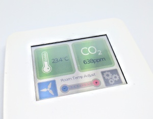
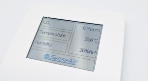
With that in mind lets see what type of tSense you have. There's two main ones, the EFA model and the standard model (see different GUI below). The hardware is the same (K70) but different firmware separates them. No one is better then the other, they are just different.
The EFA model of tSense generally displays the temperature and carbon dioxide level. Other than that you have a software button for controlling the internal relay (on and off). It even have a 9 step slider used to control the indoor temperature (monitoring the status of this slider is possible using the plugin).
The standard model of tSense display temperature, humidity and carbon dioxide level on the main page. The relay can only be set to trigger by the settings menu where you can have a target level where the relay will activate.
For both models the user password for the settings is by default "1111" and for the advanced settings level the password is "2001".
Wiring
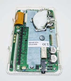
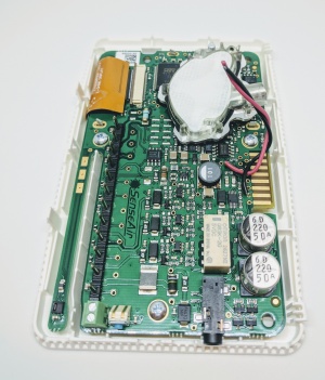
When you first open up the housing you find this:
Remove the plastic cover to expose the pcb-board:
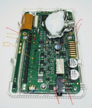
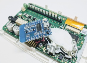
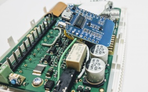
To get power and ground to the ESP we hi-jack these vias:
Connect these to the ESPs 5V and G:
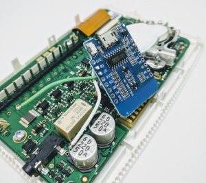
The ESP monitor the tSense through the serial ports, green to D7 (GPIO-13) and white to D8 (GPIO-15):
Use the 3.5mm pads or the vias on the tSense:
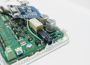
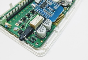
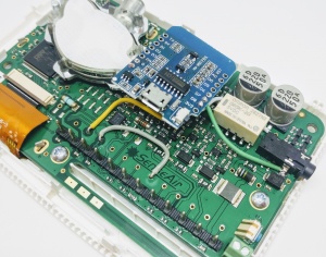
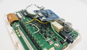
To monitor the relay you need to take the ground - gray - from 7th via (from the top) and either connect it as in the picture below (which gives the relay a normal open mode) or to the first via (which gives the relay a normal closed mode). The yellow cable is connected to the communication side of the relay and then connected to the ESPs D6 (GPIO-12). As of later versions of the plugin you can also trigger the relay using these commands (http://<espeasyip>/control?cmd=senseair_setrelay,<value>, also work within rules and from MQTT messages):
| Command | Value | Extra information |
|---|---|---|
| senseair_setrelay,<value> | 1 | Trigger the relay ON |
| 0 | Trigger the relay OFF | |
| -1 | Current plugin take over the control of the internal tSense control of the relay, setting the senseair_setrelay=-1 will reset this. |
If you use ESP Easy to control the relay you can skip the soldering of the yellow and gray cables but it is not a problem if you have them (you get a double feedback that the relay is active/inactive).
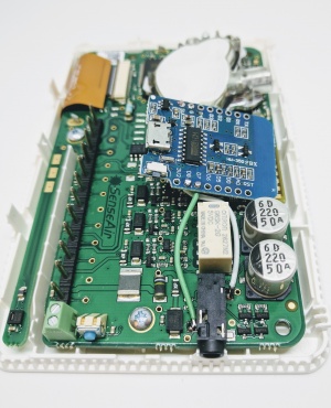
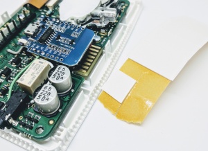
To fixate the ESP board you could use a tape pad with double sided adhesive:
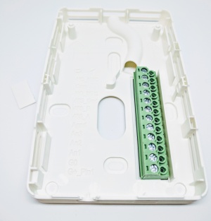
Before re-positioning the unit onto the back panel you need to remove a plastic wall (just bend it and it will break):
DONE! Power up using the tSense's 24VDC/24VAC (the unit is possible to function with input power 9VDC - 24VDC with no problem) power adaptor and setup the ESP Easy according to the next section.
ESP Easy
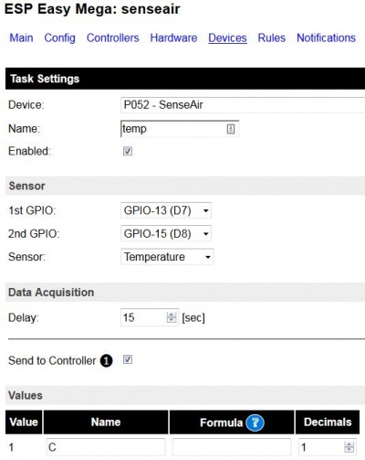
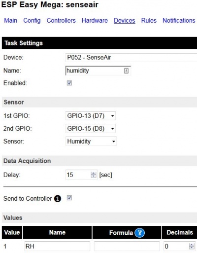
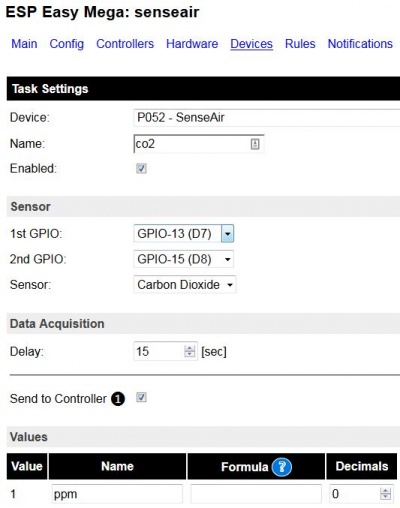
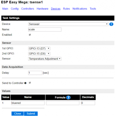
Setting up the tSense unit with the ESP Easy firmware is pretty straight forward. P052 Senseair is the name of the device plugin and you set it up as follows.
Temperature
Humidity
Carbon Dioxide
Temperature Adjustment
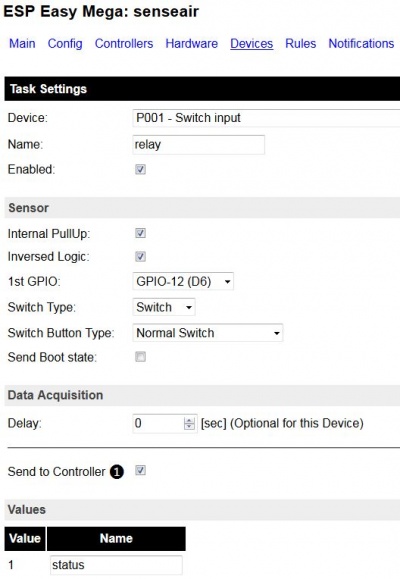
Switch monitor status of relay is using the standard plugin for a switch (P001 Switch input).
Please observe that you cannot CONTROL the relay using this method, only monitor its status. To control the relay you need the latest plugin and use senseair_setrelay command.
Indicators (recommended settings)
| Indicator | Value Name | Delay (sec) | Decimals | Extra information |
|---|---|---|---|---|
| Error Status | Error | 15 | 0 | Used to present errors (if any): "-1" No error "0" No ability to communicate with CO2 sensor module. "1" CO2 measurement error. "2" Temp measurement error. "3" No ability to communicate with RH/T sensor module. "4" RH measurement error "5" Temp measurement error, sensor will use CO2 sensor temperature if RH/T temperature is unavailable. S_Temp will be set to NTC_Temp. "6" (not used) "7" (not used) "8" Error in output configuration. Output is still updated, i.e. can be 0-10V. "9" One or several bytes of sensors parameter memory (settings) are corrupt. |
| Carbon Dioxide | ppm | 15 | 0 | |
| Temperature | °C | 15 | 1 | |
| Humidity | %RH | 15 | 0 | |
| Temperature Adjustment | Level | 1 | 0 | This raw value goes from 0 - 1000 in 9 steps. To have them displayed as -4 to 4 use this formula: %value%*0.008-4 To have them displayed as 1 to 9 use this formula: %value%*0.008+1 |
| Relay Status | Relay | 1 | 0 | This indicator monitor the software relay status, whereas the yellow/gray wiring monitor the hardware relay status (it's actual output). Both methods are good, just different. The software way of monitoring the status might be up to 1 second longer (if delay is 1 sec) due to the fact that a switch status is send instant compared to the relay status indicator which is sent once every X seconds. |
