Difference between revisions of "Breadboards"
| (4 intermediate revisions by one other user not shown) | |||
| Line 1: | Line 1: | ||
| − | + | [[File:WIP.gif]] | |
[[File:IMG 20160228 143153537.jpg]] | [[File:IMG 20160228 143153537.jpg]] | ||
| Line 14: | Line 14: | ||
What can you expect on breadboards and how can you suppress it? | What can you expect on breadboards and how can you suppress it? | ||
| − | 1 - bad contact | + | 1 - bad contact |
| − | 2 - picking up rf transients | + | 2 - picking up rf transients |
| − | 3 - resistance | + | 3 - resistance |
| + | |||
| + | |||
| + | [[File:Bread2.png]] | ||
| + | |||
| + | Another fine example, contributed by tozett | ||
| + | |||
| + | When you start working with a breadboard for the first time, there is something you need to keep in mind. | ||
| + | The smaller breadboards are usually quite straightforward: a block of plastic with holes, with underlying connectors vertically. Compare this with a spreadsheet, where the columns are interconnected and the rows are not. | ||
| + | |||
| + | On the larger models, you will see two rows on the top and the bottom that are horizontally connected. Usually they are colorcoded red and white: you guessed it, this is meant for power. Connect a power supply on one side, and the horizontal bars allow vcc and ground. The top and bottom bars are not connected, so you could put 5V on one bar, and 3.3 on the other. | ||
| + | In webshops you will even find a special powersupply that you can mount onto the breadboard. Plug in a USB cable into the power supply, and you have 5V and/or 3.3V, to be configured with a set of jumpers. | ||
| + | |||
| + | So far, so good. WHen you buy a new breadboard, it makes sense to add the special power supply to your order. | ||
| + | |||
| + | But there is a snag. On some breadboard models (not all), the breadboard is actually devided into four parts. The left and right half are not connected (this applies to the power bars on top and bottom). Also, the top half and bottom half are not connected: this applies to the middle (working) part. | ||
| + | Once you know this, you can make use of it. If you don't want this, simply plug in a couple of jumper cables to connect the halves. | ||
Latest revision as of 20:49, 9 October 2017
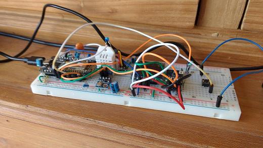
Need I say more? A breadboard, however very handy during the creative process, also incorporates many weird phenomena, we call unexpected behavior.
Any wire electronically consists of a network of resistors, coils and capacitors. Especially in high frequency environments, this can cause problems in electronic circuits. If you want to learn more about this interesting subject, there is enough of it on the WWW. For instance [1]
Most of these problems occur at high frequencies, but do not be mistaken, the ESP is just that, a high frequent circuit. Also something simple as flipping a switch easily causes interesting high frequent transients.
What can you expect on breadboards and how can you suppress it?
1 - bad contact
2 - picking up rf transients
3 - resistance
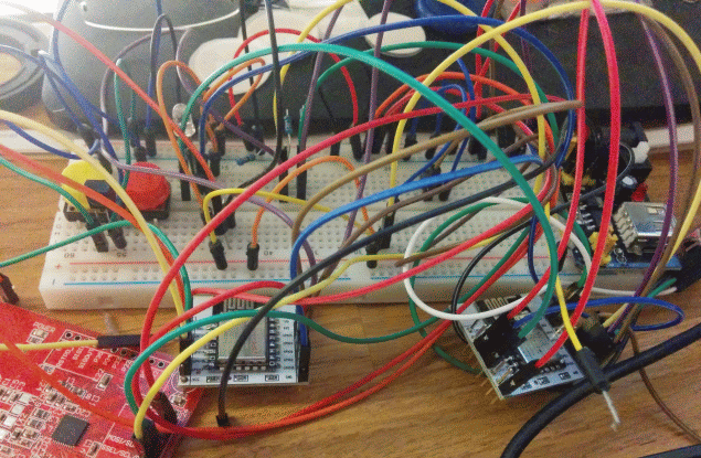
Another fine example, contributed by tozett
When you start working with a breadboard for the first time, there is something you need to keep in mind. The smaller breadboards are usually quite straightforward: a block of plastic with holes, with underlying connectors vertically. Compare this with a spreadsheet, where the columns are interconnected and the rows are not.
On the larger models, you will see two rows on the top and the bottom that are horizontally connected. Usually they are colorcoded red and white: you guessed it, this is meant for power. Connect a power supply on one side, and the horizontal bars allow vcc and ground. The top and bottom bars are not connected, so you could put 5V on one bar, and 3.3 on the other. In webshops you will even find a special powersupply that you can mount onto the breadboard. Plug in a USB cable into the power supply, and you have 5V and/or 3.3V, to be configured with a set of jumpers.
So far, so good. WHen you buy a new breadboard, it makes sense to add the special power supply to your order.
But there is a snag. On some breadboard models (not all), the breadboard is actually devided into four parts. The left and right half are not connected (this applies to the power bars on top and bottom). Also, the top half and bottom half are not connected: this applies to the middle (working) part. Once you know this, you can make use of it. If you don't want this, simply plug in a couple of jumper cables to connect the halves.


