Difference between revisions of "MCP23017"
Grovkillen (talk | contribs) (Updated command list) |
|||
| (21 intermediate revisions by one other user not shown) | |||
| Line 1: | Line 1: | ||
| − | + | = Introduction = | |
| − | + | The number of GPIO pins on the ESP module can be expanded with a IO Expander. We will use the MCP23017 that provides 16 more pins that can be used as input or output. This way it becomes possible to control a 16 channel relay board. | |
| − | |||
| − | + | Each individual pin can be used as either input or output. | |
| − | + | = Hardware = | |
| − | + | [[File:MCP23017DIP28.jpg|320px]] | |
| − | == | + | The MCP23017 needs to be connected through the I2C interface. This chip is compatible with 3V3 and it can be connected to the ESP without levelshifters.. |
| + | |||
| + | == Connections == | ||
MCP23017 ESP-01 | MCP23017 ESP-01 | ||
GND GND | GND GND | ||
VCC VCC | VCC VCC | ||
| − | SDA GPIO 0 | + | SDA GPIO 0 |
| − | SCL GPIO 2 ( | + | SCL GPIO 2 |
| + | |||
| + | = ESP Easy = | ||
| + | |||
| + | Configuration depends on how you want to use a certain port on this device. Ports are numbered 1 to 16 (if you have a single MCP23017 connected) | ||
| + | |||
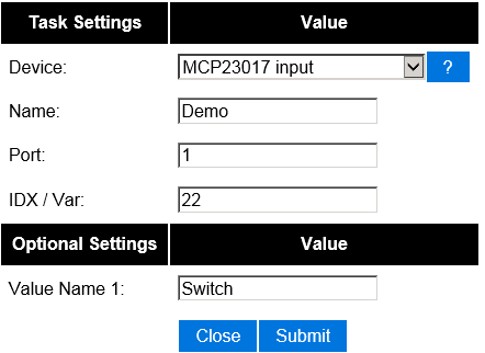
| + | == Input == | ||
| + | To have an input port act as an input switch device (just like with the default onboard GPIO pins) you need to edit a ESP Easy task and select the "MCP23017 input" device. | ||
| + | |||
| + | [[File:EasyConfigMCP.png]] | ||
| + | |||
| + | You then select the portnumber and additional configuration depending on the controller type. For Domoticz, you enter the IDX that was allocated by Domoticz for this virtual switch. | ||
| − | + | Portnumbering depends on the I2C address used: | |
| − | |||
| − | |||
{| border="1" style="border-collapse:collapse; border:1px solid silver;text-align:left;width:50%;" | {| border="1" style="border-collapse:collapse; border:1px solid silver;text-align:left;width:50%;" | ||
| − | ! | + | ! A0: |
| − | ! | + | ! A1: |
| − | ! | + | ! A2: |
| − | ! | + | ! Address: |
| + | ! Port range: | ||
| + | |- | ||
| + | | ''0'' | ||
| + | | ''0'' | ||
| + | | ''0'' | ||
| + | | 0x20 | ||
| + | | 1 - 16 | ||
| + | |- | ||
| + | | ''1'' | ||
| + | | ''0'' | ||
| + | | ''0'' | ||
| + | | 0x21 | ||
| + | | 17 - 32 | ||
| + | |- | ||
| + | | ''0'' | ||
| + | | ''1'' | ||
| + | | ''0'' | ||
| + | | 0x22 | ||
| + | | 33 - 48 | ||
| + | |- | ||
| + | | ''1'' | ||
| + | | ''1'' | ||
| + | | ''0'' | ||
| + | | 0x23 | ||
| + | | 49 - 64 | ||
|- | |- | ||
| − | | '' | + | | ''0'' |
| − | | | + | | ''0'' |
| − | | 1 | + | | ''1'' |
| − | | | + | | 0x24 |
| + | | 65 - 80 | ||
|- | |- | ||
| − | | '' | + | | ''1'' |
| − | | | + | | ''0'' |
| − | | | + | | ''1'' |
| − | | | + | | 0x25 |
| + | | 81 - 96 | ||
| + | |- | ||
| + | | ''0'' | ||
| + | | ''1'' | ||
| + | | ''1'' | ||
| + | | 0x26 | ||
| + | | 97 - 112 | ||
| + | |- | ||
| + | | ''1'' | ||
| + | | ''1'' | ||
| + | | ''1'' | ||
| + | | 0x27 | ||
| + | | 113 - 128 | ||
|} | |} | ||
| − | === | + | = Commands = |
| − | + | ||
| + | |||
| + | {| class="wikitable sortable" | ||
| + | |- | ||
| + | ! Command | ||
| + | ! Value | ||
| + | ! Extra information | ||
| + | |- | ||
| + | |||
| + | | MCPGPIO,<pin>,<value> | ||
| + | | '''1,0''' | ||
| + | | Control MCP23017 output pins (1 or 0) | ||
| + | |- | ||
| + | |||
| + | | MCPPulse,<pin>,<value>,<duration> | ||
| + | | '''1,0''' | ||
| + | | Pulse control on MCP23017 output pins (duration in mS, MILLIseconds) | ||
| + | |- | ||
| + | |||
| + | | MCPLongPulse,<pin>,<value>,<duration> | ||
| + | | '''1,0''' | ||
| + | | Pulse control on MCP23017 output pins (duration in S, seconds) | ||
| + | |- | ||
| + | |} | ||
Latest revision as of 17:55, 16 October 2017
Introduction
The number of GPIO pins on the ESP module can be expanded with a IO Expander. We will use the MCP23017 that provides 16 more pins that can be used as input or output. This way it becomes possible to control a 16 channel relay board.
Each individual pin can be used as either input or output.
Hardware

The MCP23017 needs to be connected through the I2C interface. This chip is compatible with 3V3 and it can be connected to the ESP without levelshifters..
Connections
 MCP23017 	ESP-01
 GND 	 	GND
 VCC    	VCC
 SDA		GPIO 0
 SCL		GPIO 2
ESP Easy
Configuration depends on how you want to use a certain port on this device. Ports are numbered 1 to 16 (if you have a single MCP23017 connected)
Input
To have an input port act as an input switch device (just like with the default onboard GPIO pins) you need to edit a ESP Easy task and select the "MCP23017 input" device.

You then select the portnumber and additional configuration depending on the controller type. For Domoticz, you enter the IDX that was allocated by Domoticz for this virtual switch.
Portnumbering depends on the I2C address used:
| A0: | A1: | A2: | Address: | Port range: |
|---|---|---|---|---|
| 0 | 0 | 0 | 0x20 | 1 - 16 |
| 1 | 0 | 0 | 0x21 | 17 - 32 |
| 0 | 1 | 0 | 0x22 | 33 - 48 |
| 1 | 1 | 0 | 0x23 | 49 - 64 |
| 0 | 0 | 1 | 0x24 | 65 - 80 |
| 1 | 0 | 1 | 0x25 | 81 - 96 |
| 0 | 1 | 1 | 0x26 | 97 - 112 |
| 1 | 1 | 1 | 0x27 | 113 - 128 |
Commands
| Command | Value | Extra information |
|---|---|---|
| MCPGPIO,<pin>,<value> | 1,0 | Control MCP23017 output pins (1 or 0) |
| MCPPulse,<pin>,<value>,<duration> | 1,0 | Pulse control on MCP23017 output pins (duration in mS, MILLIseconds) |
| MCPLongPulse,<pin>,<value>,<duration> | 1,0 | Pulse control on MCP23017 output pins (duration in S, seconds) |