Difference between revisions of "User:Rudy Bear"
| Line 217: | Line 217: | ||
</pre> | </pre> | ||
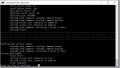
| − | so I tried | + | so I tried to modify the flash.cmd |
esptool.exe -vv -fm dout -cd nodemcu -cb 115200 -cp COM%comport% -ca 0x00000 -cf ESPEasy_R%build%_%fsize%.bin | esptool.exe -vv -fm dout -cd nodemcu -cb 115200 -cp COM%comport% -ca 0x00000 -cf ESPEasy_R%build%_%fsize%.bin | ||
| − | but the new -fm breaks esptool.exe | + | but the new -fm switch breaks esptool.exe |
== Flashing via Raspberry Pi == | == Flashing via Raspberry Pi == | ||
Revision as of 15:05, 4 November 2017
I'm attempting to use Sonoff hardware with the ESP-Easy firmware as a route to simple home automation, and data collection. I'm not trying to pass all of this off as my own work, I'm definitely 'Standing on the shoulders of giants' [1]
Contents
- 1 Background - why am I doing this
- 2 Safety
- 3 Opening up the Sonoff
- 4 Soldering the header
- 5 Downloading the Software
- 6 Flashing via win and USB to TTL
- 7 Flashing via Raspberry Pi
- 8 Basic Set up
- 9 How to control the relay via http
- 10 How to add a D12D18 temp sensor
- 11 How to Read the temp sensor
- 12 References
Background - why am I doing this
I currently use a Raspberry Pi (RPi) to control my Central Heating. I have a series of (hardwired) temperature sensors in a few rooms in my house, the central heating boiler is controlled via a relay on the old thermostat wires, and I have a single solenoid controlled radiator value.
The RPi senses the temperature sensors every minute, and depending on the time of day and the temperature will activate the relay thus starting the boiler.
My living room heats up quite quickly due to a large radiator, and this switches off the Central Heating leaving other rooms colder than I'd like, so I've replaced the standard thermostatic radiator valve (TRV) in the living room with a valve that can be switched via a relay.
The system has been working well for the last year or so, and I've slowly added extra sensors and features, including an external temperature sensor and an atmospheric pressure sensor. My Central Heating control became sentient, and now tweets data - SwanPondWeather.
What irritates me is the large box that houses the relays and the fact that I have 240v (admittedly in a secure screwed down box) quite close to the RPi.
This page tries to describe my move to wifi controlled switches


Safety
The Sonoff boxes are quite small, and they have 240v running though them - If you don't know what you're doing, that will kill you. I will describe the modification that I've made to the Sonoff boxes, but this requires a small amount of soldering skill. If you're not confident that you can do this, then enjoy reading about the experience, but don't be tempted to get out that soldering iron.
- When flashing the Sonoff, always use the 3.3v pin, always disconnect the 240v supply
- Always ensure the Sonoof is reassembled in it's box before connecting the 240v supply
Opening up the Sonoff
Disconnect everything before attempting to open it up.
Luckily opening up a Sonoff is really easy - if you have protruding fingernail, you can use that to split the two parts the the case apart.
There is a little paper tamper maker on the side, so if you open it then your warranty is null and void.

The Sonoff

Cracking it open
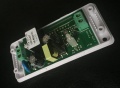
Opened up


Soldering the header
To be able to do anything useful with the Sonoff we have to be able to flash the Sonoff with the ESP-Easy software, and to do that we need to be able to connect the Sonoff to something! To make that easier we're going to solder some pins onto the circuit board.
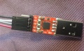
The circuit board designer has made this fairly easy by giving us a row of standard pitch holes that we can connect some header pins.
I purchased the pins from eBay (search for SIL 2.54mm header) - broke off 5 pins, and then dug out the soldering iron. You have to solder from the other side, so it's a good idea to hold the pins in place with some sticky tape, so that when you turn it to start soldering they don't just fall out!

Five pins ready to go
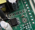
Where the pins are going
All done (Pin 1 on the left Pin 5 on the right)


Great - so what does that get you? Firstly a way of safely powering the Sonoff with 3.3v while flashing the firmware (so much better than 240v), secondly the tx and rx lines to send the new firmware down, and thirdly (as a bonus) GPIO14 - and we're going to use this later in the project.
| Pin Number | Name | Notes |
|---|---|---|
| 1 | 3.3v | |
| 2 | RX | |
| 3 | TX | |
| 4 | Ground | |
| 5 | GPIO14 |
Downloading the Software
You can download the pre-compiled ready to use ESP-Easy software as a zip file.
the version I used can be found here http://www.letscontrolit.com/downloads/ESPEasy_R120.zip - but it's worth checking to see if there's a newer version by now!
what's in the zip file?
- ESPEasy_R120_1024.bin - the pre-packaged firmware for a EPS8266 with 1mb of ram
- ESPEasy_R120_4096.bin - the pre-packaged firmware for a EPS8266 with 4mb of ram
- ESPEasy_R120_512.bin - the pre-packaged firmware for a EPS8266 with 0.5mb of ram
- esptool.exe - a DOS version on the python esptool
- flash.cmd - a wrapper around esptool that makes it easier to use
- Source/ - all the source code, so you can modify it to your hearts content
What does flash.cmd do?
$ cat flash.cmd
@echo off
set /p comport= Comport (example 3, 4, ..)           :
set /p fsize= Flash Size (example 512, 1024, 4096) :
set /p build= Build (example 71, 72, ..)           :

echo Using com port: %comport%
echo Using bin file: ESPEasy_R%build%_%fsize%.bin

esptool.exe -vv -cd nodemcu -cb 115200 -cp COM%comport% -ca 0x00000 -cf ESPEasy_R%build%_%fsize%.bin

pause
So this wrapper allows you to control the comm port, select the ram size, and the build number.
Flashing via win and USB to TTL
You might want to read all of this section before buying a USB->TTL board. - see #This doesn't work
I'd viewed some YouTube videos on how to flash the firmware - How to flash Sonoff to ESP Easy firmware is a good example, and he uses a windows box with a USB->TTL board to blow the firmware, so I decided to follow his example.
off to ebay again - searching for "CP2102 USB TTL" should get you a USB -> TTL which will allow you to connect your Sonoff to your Windows machine.
I had to download a driver to get Windows to recognise the USB -> TTL as a comm port - I think I used this driver
Once you've installed the driver, when you plug the device into a USB port, if you start up your "Device Manager" and click on "Ports (COM & LPT} you should see your "USB to UART Bridge" allocated to a Comm port - if not, you'll need to play with the drivers (good luck).
Make a note of the comm port - you'll need it in a moment.
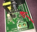
Making the connections
There's only four connections you need to make, and I used some jumper wires. If you're lucky there will be markings on the USB->TTL device.
you need to connect
- 3.3v to 3.3v
- TX to TX
- RX to RX
- Gnd to Gnd
Stay away from +5v and the GIPO pin
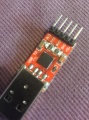
the USB->TTL device

windows driver screen
connections at the USB->TTL
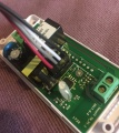
Connections at the Sonoff


Finally - we get to blow the firmware
open up a command prompt and head to the directory you unzipped the software into.
Meanwhile insert the USB -> TTL board, that's connected to the Sonoff while holding the push button on the Sonoff - This enables the flash mode on the Sonoff. (you can let go of the button after a second or so!)
on the command line:
> flash
now you get three questions
- Comport (I told you'd need it)
- Flash Size
- Build
So I used, 7, 1024, and 120.
After a bit you should see a bunch of dots scrolling across the screen - that's good news - the firmware is being blown.
If you see a screen which repeats 'trying to connect' you might try swapping the TX and RX lines.
If you get a "starting app with reboot" message you might well have blown the new firmware
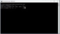
input data
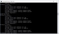
no connection
finished


How do you know it's worked?
Unplug the USB, wait a few seconds, and plug it back in. No need to press the button.
Now use your PC or (better) your smart phone to see if you can see a new wifi network ESP-0
This doesn't work
No it doesn't does it!
I got very frustrated at this point - there's a some noise on the internet about a fake USB -> TTL boards, and it's true I only paid a couple of pounds for my board.
but then I found this - https://github.com/arendst/Sonoff-Tasmota/wiki/Theo's-Tasmota-Tips
20170714 - Tasmota needs compile Flash Mode option DOUT on all devices

An increasing number of devices is using the ESP8285. As this chip only supports a subset of hardware connections to it's inbuilt 1MB flash the firmware needs to be compiled with Flash Mode option set for DOUT.

This is documented in the Wiki and the platformio.ini file in the repository.

As this compile option works for the ESP8266 "legacy" chip too I only provide released firmware compiled with Flash Mode DOUT which runs fine on all released hardware like Sonoff, Wemos etc. See also #598.

Indications of selecting the wrong Flash Mode compile option (like DIO or QIO) on ESP8285 is a dead device while uploading just went fine #683.
...which is exactly what I'm getting, and this is very recent. The "game is afoot"!
So esptool.py (https://github.com/espressif/esptool/blob/master/esptool.py) does have the ability to use the DOUT mode, the bad news is that esptool.exe (or at least the version I have) doesn't have that switch.
in esptool.py you have a switch
        parent.add_argument('--flash_mode', '-fm', help='SPI Flash mode',
choices=extra_keep_args + ['qio', 'qout', 'dio', 'dout'],
so I tried to modify the flash.cmd
esptool.exe -vv -fm dout -cd nodemcu -cb 115200 -cp COM%comport% -ca 0x00000 -cf ESPEasy_R%build%_%fsize%.bin
but the new -fm switch breaks esptool.exe