Difference between revisions of "Sonoff DIY 4ch"
Jump to navigation
Jump to search
Grovkillen (talk | contribs) (Created page with "= Introduction = The Sonoff DIY 4ch is a relay unit to be used as retrofit. It is based on the ESP8285 chip and can control four relays. = Hardware = File:Sonoff DIY 4ch...") |
Grovkillen (talk | contribs) |
||
| (3 intermediate revisions by the same user not shown) | |||
| Line 10: | Line 10: | ||
* Flash size: 1M | * Flash size: 1M | ||
* Onboard USB-TTL converter: No | * Onboard USB-TTL converter: No | ||
| − | * GPIO's broken out/available to free use: | + | * GPIO's broken out/available to free use: 0, 9, 10, 14 (vias) |
* GPIO tied to onboard hardware: 4, 5, 12, 15 (Relay 10A@230VAC), 13 (LED red) | * GPIO tied to onboard hardware: 4, 5, 12, 15 (Relay 10A@230VAC), 13 (LED red) | ||
| − | + | * Power supply information: 7-32VDC or 5VDC (USB) | |
| − | * Power supply information: | ||
* Antenna: onboard PCB antenna | * Antenna: onboard PCB antenna | ||
| Line 28: | Line 27: | ||
'''Programmer''' '''ESP''' | '''Programmer''' '''ESP''' | ||
TX <--> RX (fourth pin seen in picture above) | TX <--> RX (fourth pin seen in picture above) | ||
| − | RX <--> TX ( | + | RX <--> TX (third pin seen in picture above) |
'''Power''' | '''Power''' | ||
| − | 7-32V <--> VCC (input power, also | + | 7-32V <--> VCC (input power, also 5V USB can also be used) |
GND <--> GND (input power) | GND <--> GND (input power) | ||
In order to get the unit in flash mode the GPIO-0 needs to be LOW. If you have soldered pin headers to the "key" vias you can use a jumper between "COM" and "KEY1". | In order to get the unit in flash mode the GPIO-0 needs to be LOW. If you have soldered pin headers to the "key" vias you can use a jumper between "COM" and "KEY1". | ||
Latest revision as of 23:04, 2 December 2017
Introduction
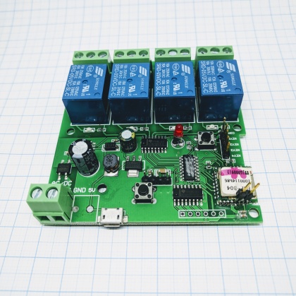
The Sonoff DIY 4ch is a relay unit to be used as retrofit. It is based on the ESP8285 chip and can control four relays.
Hardware
- ESP chip version: ESP8285
- Flash size: 1M
- Onboard USB-TTL converter: No
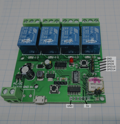
- GPIO's broken out/available to free use: 0, 9, 10, 14 (vias)
- GPIO tied to onboard hardware: 4, 5, 12, 15 (Relay 10A@230VAC), 13 (LED red)
- Power supply information: 7-32VDC or 5VDC (USB)
- Antenna: onboard PCB antenna
GPIO 0, 9, 10, 14 are available on the board, marked with "key" 1, 2, 3, 4.
Wiring/flashing
A programmer is needed to flash this device.
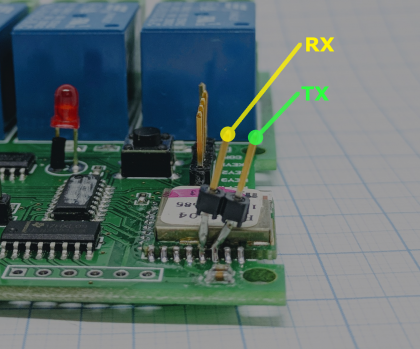
  Programmer     ESP
  TX      <-->   RX (fourth pin seen in picture above)
  RX      <-->   TX (third pin seen in picture above)

  Power
  7-32V    <-->   VCC (input power, also 5V USB can also be used)
  GND     <-->   GND (input power)
In order to get the unit in flash mode the GPIO-0 needs to be LOW. If you have soldered pin headers to the "key" vias you can use a jumper between "COM" and "KEY1".


