Difference between revisions of "ESP-01"
Jump to navigation
Jump to search
Grovkillen (talk | contribs) (Created page with "= Introduction = The ESP-01 is one of the smallest units available. Compared to other ESP units it is powered directly and thus need to be fed with 3.3V and not 5V. Two gener...") |
Grovkillen (talk | contribs) |
||
| Line 30: | Line 30: | ||
GND <--> GND | GND <--> GND | ||
| − | In order to get the unit in flash mode the GPIO-0 needs to be LOW and the CH-EN need to be set to high. The CH-EN can be connected to the VDD, in the pictures a jumper is soldered between these but you could use a resistor to make sure that no over current hurt the unit. | + | In order to get the unit in flash mode the GPIO-0 needs to be LOW and the CH-EN need to be set to high. The CH-EN can be connected to the VDD, in the pictures a jumper is soldered between these but you could '''use a resistor to make sure that no over current hurt the unit'''. |
Revision as of 09:56, 17 January 2018
Introduction
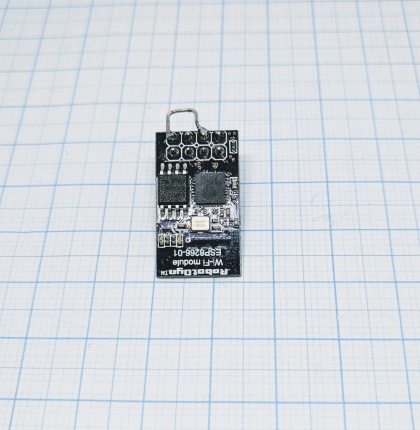
The ESP-01 is one of the smallest units available. Compared to other ESP units it is powered directly and thus need to be fed with 3.3V and not 5V. Two general GPIOs are available and if you need more you can use the two serial ports (1,3 / RX,TX).
Hardware
- ESP chip version: ESP8266
- Flash size: 1M
- Onboard USB-TTL converter: No
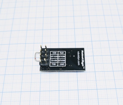
- GPIO's broken out/available to free use: 0, 2
- Power supply information: 3.3VDC
- Antenna: onboard PCB antenna
Wiring/flashing
A programmer is needed to flash this device.
  Programmer     ESP
  TX      <-->   RX
  RX      <-->   TX

  Power
  3.3V    <-->   VDD
  GND     <-->   GND
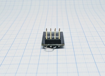
In order to get the unit in flash mode the GPIO-0 needs to be LOW and the CH-EN need to be set to high. The CH-EN can be connected to the VDD, in the pictures a jumper is soldered between these but you could use a resistor to make sure that no over current hurt the unit.


