Difference between revisions of "Sonoff Touch"
Grovkillen (talk | contribs) |
Grovkillen (talk | contribs) |
||
| (21 intermediate revisions by the same user not shown) | |||
| Line 1: | Line 1: | ||
= Introduction = | = Introduction = | ||
| + | |||
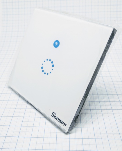
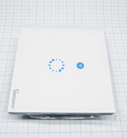
| + | The Sonoff Touch is a touch controlled panel wall switch. It is based on the ESP8285 chip and can control one relay. Behind the blue tape there's a LED which you can control as you like. Other than normal on or off when the ceiling light (or what ever you control with the relay) you might want to flash it on-off-on-off when the morning news paper is delivered to your mailbox. | ||
| + | |||
| + | = Hardware = | ||
[[File:Sonoff-Touch-001.jpg|420px]] | [[File:Sonoff-Touch-001.jpg|420px]] | ||
| Line 10: | Line 14: | ||
* Power supply information: 90-250VAC | * Power supply information: 90-250VAC | ||
* Antenna: onboard PCB antenna | * Antenna: onboard PCB antenna | ||
| − | |||
| − | |||
[[File:Sonoff-Touch-002.jpg|420px]] | [[File:Sonoff-Touch-002.jpg|420px]] | ||
== Wiring/flashing == | == Wiring/flashing == | ||
| + | |||
| + | A programmer is needed to flash this device. | ||
| + | |||
| + | '''Programmer''' '''ESP''' | ||
| + | TX <--> RX (2nd via) | ||
| + | RX <--> TX (3rd via) | ||
| + | |||
| + | '''Power''' | ||
| + | 3.3V <--> VCC (1st via [square]) | ||
| + | GND <--> GND (4th via) + GPIO-0 | ||
| + | |||
| + | In order to get the ESP8285 in flash mode the GPIO-0 needs to be LOW. (See picture with explanations below) | ||
| + | Remember to remove GND from GPIO-0 once flashed. | ||
| + | ---- | ||
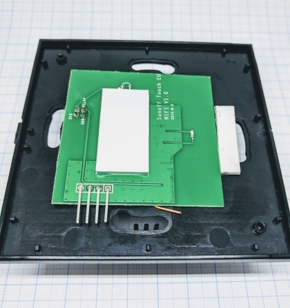
| + | Already soldered board fitted in the casing. | ||
[[File:Sonoff-Touch-003.jpg|420px]] | [[File:Sonoff-Touch-003.jpg|420px]] | ||
| + | |||
| + | Soldered board seen from front. | ||
[[File:Sonoff-Touch-004.jpg|420px]] | [[File:Sonoff-Touch-004.jpg|420px]] | ||
| + | |||
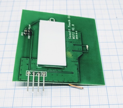
| + | Soldered board seen from bottom, square via as far left out of the four. | ||
[[File:Sonoff-Touch-005.jpg|420px]] | [[File:Sonoff-Touch-005.jpg|420px]] | ||
| + | = ESP Easy = | ||
| + | |||
| + | '''Devices''' | ||
| + | |||
| + | [[File:Sonoff touch 001.PNG|520px]] | ||
| + | |||
| + | ---- | ||
| + | '''Switch''' | ||
| + | |||
| + | [[File:Sonoff touch 002.PNG|520px]] | ||
| + | |||
| + | '''Push button active high''' will make the relay pull when button is released, '''push button active low''' will pull the relay (instantaneously) when button is touched. What you prefer. | ||
| + | |||
| + | ---- | ||
| + | '''Relay''' | ||
| + | |||
| + | [[File:Sonoff touch 003.PNG|520px]] | ||
| + | |||
| + | ---- | ||
| + | '''Switch to Relay rule''' | ||
| + | |||
| + | <pre style="color: #0077dd"> | ||
| + | on touch#switch do | ||
| + | if [touch#switch]=1 | ||
| + | gpio,12,1 | ||
| + | else | ||
| + | gpio,12,0 | ||
| + | endif | ||
| + | endon | ||
| + | </pre> | ||
| + | |||
| + | '''LED rule''' | ||
| + | |||
| + | Depending if you want the LED to be on or off when the relay is open/closed you may use this rule: | ||
| + | |||
| + | <pre style="color: #0077dd"> | ||
| + | on relay#switch do | ||
| + | if [relay#switch]=1 //change this [relay#switch]=0 for LED off when relay is closed | ||
| + | gpio,13,1 | ||
| + | else | ||
| + | gpio,13,0 | ||
| + | endif | ||
| + | endon | ||
| + | </pre> | ||
| − | + | To control the brightness you may use the PWM command instead of GPIO command. | |
Latest revision as of 11:26, 2 April 2018
Introduction
The Sonoff Touch is a touch controlled panel wall switch. It is based on the ESP8285 chip and can control one relay. Behind the blue tape there's a LED which you can control as you like. Other than normal on or off when the ceiling light (or what ever you control with the relay) you might want to flash it on-off-on-off when the morning news paper is delivered to your mailbox.
Hardware
- ESP chip version: ESP8285
- Flash size: 1M
- Onboard USB-TTL converter: No
- GPIO's broken out/available to free use: None
- GPIO tied to onboard hardware: 0 (button), 12 (Relay 2A@230VAC), 13 (LED blue)
- Power supply information: 90-250VAC
- Antenna: onboard PCB antenna
Wiring/flashing
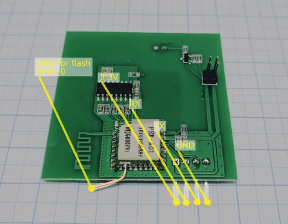
A programmer is needed to flash this device.
  Programmer     ESP
  TX      <-->   RX (2nd via)
  RX      <-->   TX (3rd via)

  Power
  3.3V    <-->   VCC (1st via [square])
  GND     <-->   GND (4th via) + GPIO-0
In order to get the ESP8285 in flash mode the GPIO-0 needs to be LOW. (See picture with explanations below)
Remember to remove GND from GPIO-0 once flashed.
Already soldered board fitted in the casing.
Soldered board seen from front.
Soldered board seen from bottom, square via as far left out of the four.
ESP Easy
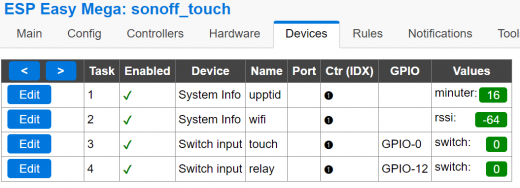
Devices
Switch
Push button active high will make the relay pull when button is released, push button active low will pull the relay (instantaneously) when button is touched. What you prefer.
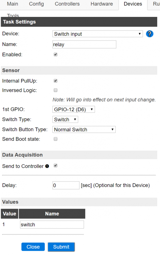
Relay
Switch to Relay rule
 on touch#switch do
  if [touch#switch]=1
   gpio,12,1
  else
   gpio,12,0
  endif
 endon
LED rule
Depending if you want the LED to be on or off when the relay is open/closed you may use this rule:
 on relay#switch do
  if [relay#switch]=1 //change this [relay#switch]=0 for LED off when relay is closed
   gpio,13,1
  else
   gpio,13,0
  endif
 endon
To control the brightness you may use the PWM command instead of GPIO command.
