Difference between revisions of "Rotary Encoder"
Grovkillen (talk | contribs) |
Grovkillen (talk | contribs) |
||
| (7 intermediate revisions by the same user not shown) | |||
| Line 1: | Line 1: | ||
= Introduction = | = Introduction = | ||
| − | A | + | A rotary encoder can be used in many applications that require precise (unlimited) rotation indication. A general use is to have the encoder set the volume of a speaker or position of a stepper motor. |
| + | |||
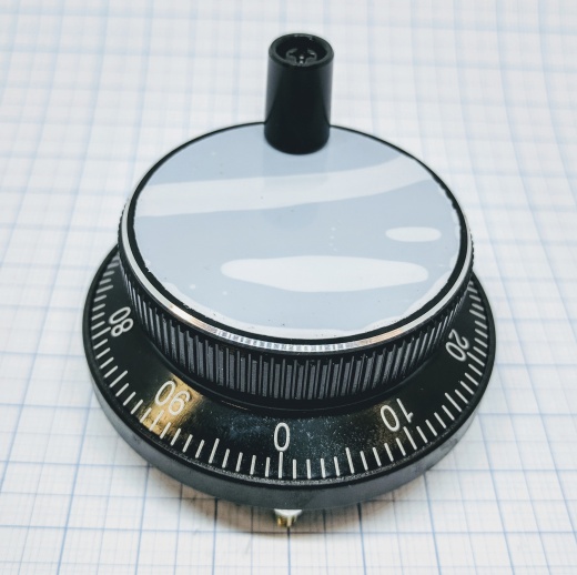
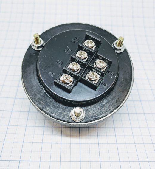
| + | A pulse wheel used for CNC machines. | ||
[[File:Pulse wheel.jpg|520px]] | [[File:Pulse wheel.jpg|520px]] | ||
| − | + | [[File:Pulse wheel 002.jpg|520px]] | |
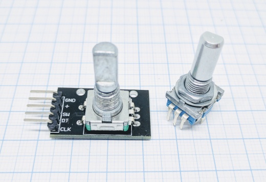
| − | + | A rotary encoder used for volume and GUI interaction (press the knob for switch input). | |
[[File:Rotary encoder 001.jpg|520px]] | [[File:Rotary encoder 001.jpg|520px]] | ||
= Hardware = | = Hardware = | ||
| − | |||
| − | |||
| − | |||
| − | |||
| − | |||
| − | A and B is sometimes labeled CLK and DT, other labels might also be used. Test and see what works for your encoder. If the rotary encoder have A- and B- ports it is ideal to use them since the pulses are negative and doesn't strain the ESP unit's power. Using a positive signal is not a problem though. | + | '''ESP''' '''Encoder''' |
| + | GPIO <--> A or CLK | ||
| + | GPIO <--> B or DT | ||
| + | GPIO* <--> I (optional) | ||
| + | |||
| + | '''Power''' | ||
| + | 3.3V <--> VCC/+ | ||
| + | GND <--> GND/V0 | ||
| + | |||
| + | *if any is available, used to "0" the counter after each turn. | ||
| + | Switch A/B if the encoder is counting backwards! | ||
| + | |||
| + | |||
| + | A and B is sometimes labeled CLK and DT, other labels might also be used. Test and see what works for your encoder. If the rotary encoder have A- and B- ports it is ideal to use them since the pulses are negative and doesn't strain the ESP unit's power. Using a positive signal is not a problem though. '''Do not use GPIO 16''' for this plugin, it will not work properly. | ||
= ESP Easy = | = ESP Easy = | ||
| − | Use the device tab on the ESP Easy web interface and create a new task by editing one of the available tasks. Select "Switch input - ..." from the drop down box. | + | Use the device tab on the ESP Easy web interface and create a new task by editing one of the available tasks. Select "Switch input - ..." from the drop down box. Max four rotary encoder devices can be used on the same ESP Easy unit. To enable the switch input (press the knob) you need to set this as a generic switch input and connect the "SW" pin with the GND (or 3.3V if the pin is normal low). |
| + | |||
[[File:Rotary encoder ESP EASY.PNG|520px]] | [[File:Rotary encoder ESP EASY.PNG|520px]] | ||
| − | Mode: sets the "resolution" of the turning on the knob. 1 pulse per cycle is "slowest"/finest and 4 pulses per cycle is the "fastest"/coarsest. | + | '''Mode''': sets the "resolution" of the turning on the knob. 1 pulse per cycle is "slowest"/finest and 4 pulses per cycle is the "fastest"/coarsest. |
| − | Limit min: is the lowest value that the counter will go to. Observe that if you have the counter on a value below this limit the counter will climb above this value but not below it once it has reached the min limit. | + | '''Limit min''': is the lowest value that the counter will go to. Observe that if you have the counter on a value below this limit the counter will climb above this value but not below it once it has reached the min limit. |
| − | Limit max: is the highest value that the counter will go to. As with the min limit if the counter is above this limit it will descend to the max level but never climb over it once reached below it. | + | '''Limit max''': is the highest value that the counter will go to. As with the min limit if the counter is above this limit it will descend to the max level but never climb over it once reached below it. |
Latest revision as of 10:18, 11 November 2018
Introduction
A rotary encoder can be used in many applications that require precise (unlimited) rotation indication. A general use is to have the encoder set the volume of a speaker or position of a stepper motor.
A pulse wheel used for CNC machines.
A rotary encoder used for volume and GUI interaction (press the knob for switch input).
Hardware
    ESP            Encoder
    GPIO    <-->   A or CLK
    GPIO    <-->   B or DT
    GPIO*   <-->   I (optional)

    Power
    3.3V    <-->   VCC/+
    GND     <-->   GND/V0

*if any is available, used to "0" the counter after each turn.
Switch A/B if the encoder is counting backwards!
A and B is sometimes labeled CLK and DT, other labels might also be used. Test and see what works for your encoder. If the rotary encoder have A- and B- ports it is ideal to use them since the pulses are negative and doesn't strain the ESP unit's power. Using a positive signal is not a problem though. Do not use GPIO 16 for this plugin, it will not work properly.
ESP Easy
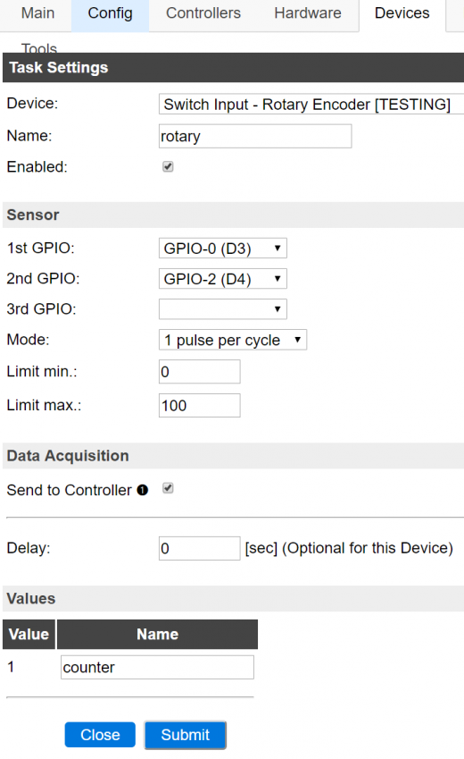
Use the device tab on the ESP Easy web interface and create a new task by editing one of the available tasks. Select "Switch input - ..." from the drop down box. Max four rotary encoder devices can be used on the same ESP Easy unit. To enable the switch input (press the knob) you need to set this as a generic switch input and connect the "SW" pin with the GND (or 3.3V if the pin is normal low).
Mode: sets the "resolution" of the turning on the knob. 1 pulse per cycle is "slowest"/finest and 4 pulses per cycle is the "fastest"/coarsest.
Limit min: is the lowest value that the counter will go to. Observe that if you have the counter on a value below this limit the counter will climb above this value but not below it once it has reached the min limit.
Limit max: is the highest value that the counter will go to. As with the min limit if the counter is above this limit it will descend to the max level but never climb over it once reached below it.


