Difference between revisions of "Main Page"
Jump to navigation
Jump to search
| Line 12: | Line 12: | ||
{| class="wikitable" | {| class="wikitable" | ||
| − | !colspan="2" style="font-size:24px; background-color: | + | !colspan="2" style="font-size:24px; color:white; background-color: black;"|Sensors (Input) |
|- | |- | ||
| − | |style="font-size:16px; background-color: # | + | |style="font-size:16px; color:white; background-color: #0077dd;" align="center"| PulseCounting || style="font-size:16px; color:white; background-color: #0077dd;" align="center"| Temperature |
|- | |- | ||
| [[PulsCounter | TCR5000]] [[File:TCR5000.jpg|100px|link=]] || [[TemperatureSensor | Dallas DS18b20]] [[File:DS18B20.jpg|100px|link=]] | | [[PulsCounter | TCR5000]] [[File:TCR5000.jpg|100px|link=]] || [[TemperatureSensor | Dallas DS18b20]] [[File:DS18B20.jpg|100px|link=]] | ||
|- | |- | ||
| − | |style="font-size:16px; background-color: # | + | |style="font-size:16px; color:white; background-color: #0077dd;" align="center"| Barometric Pressure || style="font-size:16px; color:white; background-color: #0077dd;" align="center"|Lux |
|- | |- | ||
| [[BarometricSensor | BMP085]] [[File:BMP085.png|100px|link=]] || [[LuxSensor | BH1750]] [[File:BH1750.jpg|320px|100px|link=]] | | [[BarometricSensor | BMP085]] [[File:BMP085.png|100px|link=]] || [[LuxSensor | BH1750]] [[File:BH1750.jpg|320px|100px|link=]] | ||
|- | |- | ||
| − | |style="font-size:16px; background-color: # | + | |style="font-size:16px; color:white; background-color: #0077dd;" align="center"| Humidity || style="font-size:16px; color:white; background-color: #0077dd;" align="center"|RFID |
|- | |- | ||
| [[HumiditySensor | DHT]] [[File:DHT11.png|100px|link=]] || [[RFID | RFID Reader]] [[File:WiegandRFID_1.jpg|100px|link=]] | | [[HumiditySensor | DHT]] [[File:DHT11.png|100px|link=]] || [[RFID | RFID Reader]] [[File:WiegandRFID_1.jpg|100px|link=]] | ||
|- | |- | ||
| − | |style="font-size:16px; background-color: # | + | |style="font-size:16px; color:white; background-color: #0077dd;" align="center"| Distance || style="font-size:16px; color:white; background-color: #0077dd;" align="center"| Switch |
|- | |- | ||
| [[DistanceSensor | HC-SR04]] [[File:HC-SR04.jpg|100px|link=]] || [[Switch | Switch]] [[File:Lightswitch.jpg|100px|link=]] | | [[DistanceSensor | HC-SR04]] [[File:HC-SR04.jpg|100px|link=]] || [[Switch | Switch]] [[File:Lightswitch.jpg|100px|link=]] | ||
|- | |- | ||
| − | |style="font-size:16px; background-color: # | + | |style="font-size:16px; color:white; background-color: #0077dd;" align="center"| Analog || style="font-size:16px; color:white; background-color: #0077dd;" align="center"| More Analog |
|- | |- | ||
| [[ Analog | Analog]] [[File:Analog.png|100px|link=]] || [[PCF8591 | PCF8591]] [[File:PCF8591Module.jpg|100px|link=]] | | [[ Analog | Analog]] [[File:Analog.png|100px|link=]] || [[PCF8591 | PCF8591]] [[File:PCF8591Module.jpg|100px|link=]] | ||
|- | |- | ||
| − | |style="font-size:16px; background-color: # | + | |style="font-size:16px; color:white; background-color: #0077dd;" align="center"| Digital inputs || style="font-size:16px; color:white; background-color: #0077dd;" align="center"| |
|- | |- | ||
| [[MCP23017 | More inputs]] [[File:MCP23017DIP28.jpg|100px|link=]] || | | [[MCP23017 | More inputs]] [[File:MCP23017DIP28.jpg|100px|link=]] || | ||
| Line 46: | Line 46: | ||
{| class="wikitable" | {| class="wikitable" | ||
| − | !colspan="2" style="font-size:24px; background-color: | + | !colspan="2" style="font-size:24px; color:white; background-color: black;"|Actuators (Output) |
|- | |- | ||
| − | |style="font-size:16px; background-color: # | + | |style="font-size:16px; color:white; background-color: #0077dd;" align="center"| Build-in output || style="font-size:16px; color:white; background-color: #0077dd;" align="center"| |
|- | |- | ||
| [[GPIO | Output pin]] [[File:LED.png|100px|link=]] || | | [[GPIO | Output pin]] [[File:LED.png|100px|link=]] || | ||
|- | |- | ||
| − | |style="font-size:16px; background-color: # | + | |style="font-size:16px; color:white; background-color: #0077dd;" align="center"| Relais || style="font-size:16px; color:white; background-color: #0077dd;" align="center"| Extra IO |
|- | |- | ||
| [[Relais | Relais]] [[File:Relaisbordje.jpg|100px|link=]] || [[MCP23017 | More output pins]] [[File:MCP23017DIP28.jpg|100px|link=]] | | [[Relais | Relais]] [[File:Relaisbordje.jpg|100px|link=]] || [[MCP23017 | More output pins]] [[File:MCP23017DIP28.jpg|100px|link=]] | ||
| Line 60: | Line 60: | ||
{| class="wikitable" | {| class="wikitable" | ||
| − | !colspan="2" style="font-size:24px; background-color: | + | !colspan="2" style="font-size:24px; color:white; background-color: black;"|Other |
|- | |- | ||
| − | |style="font-size:16px; background-color: # | + | |style="font-size:16px; color:white; background-color: #0077dd;" align="center"| LCD || style="font-size:16px; color:white; background-color: #0077dd;" align="center"| ? |
|- | |- | ||
| [[LCDDisplay | LCD Display]] [[File:LCDConnexio.jpg|100px|link=]] || | | [[LCDDisplay | LCD Display]] [[File:LCDConnexio.jpg|100px|link=]] || | ||
Revision as of 11:20, 4 October 2015
Contents
About this Wiki
Introducing the ESP8266

Applications
| Sensors (Input) | |
|---|---|
| PulseCounting | Temperature |
TCR5000 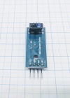 |
Dallas DS18b20 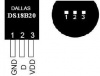
|
| Barometric Pressure | Lux |
BMP085 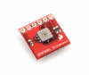 |
BH1750 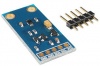
|
| Humidity | RFID |
DHT 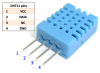 |
RFID Reader 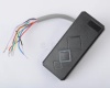
|
| Distance | Switch |
HC-SR04 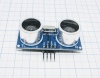 |
Switch 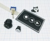
|
| Analog | More Analog |
| Analog |
PCF8591 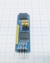
|
| Digital inputs | |
More inputs 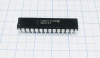 |
|
| Actuators (Output) | |
|---|---|
| Build-in output | |
Output pin 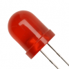 |
|
| Relais | Extra IO |
| Relais |
More output pins
|
| Other | |
|---|---|
| LCD | ? |
| LCD Display |
|
Tutorials
- Using the Arduino IDE to upload the ESP Easy firmware
- Using the ESP Easy as a simple input switch in Domoticz
- Using the ESP Easy to control a LED of Relay from OpenHAB
Firmware
