Difference between revisions of "Template Files"
Grovkillen (talk | contribs) |
Grovkillen (talk | contribs) m (→Logo) |
||
| (10 intermediate revisions by the same user not shown) | |||
| Line 1: | Line 1: | ||
Here you find different template files to use in your building or customization process. | Here you find different template files to use in your building or customization process. | ||
| − | = A4 1mm paper = | + | = Paper templates = |
| + | |||
| + | Templates used to print. | ||
| + | |||
| + | == A4 1mm paper == | ||
| + | [[File:1mm_A4_paper_EXAMPLE.jpg|520px]] | ||
| + | |||
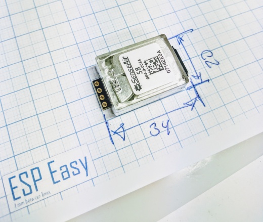
This template is mainly used when taking pictures and/or measuring different units and devices. We officially use this template when documenting (by picture) the devices that we use with the plugins etc. The lines are 1mm apart and the somewhat thicker lines are 5mm apart, the thickest lines are 10mm apart. Please remember to print the page as "true size" in order to maintain these dimensions on the printed paper.<br/> | This template is mainly used when taking pictures and/or measuring different units and devices. We officially use this template when documenting (by picture) the devices that we use with the plugins etc. The lines are 1mm apart and the somewhat thicker lines are 5mm apart, the thickest lines are 10mm apart. Please remember to print the page as "true size" in order to maintain these dimensions on the printed paper.<br/> | ||
[https://www.letscontrolit.com/wiki/images/c/c0/ESP_Easy_1mm_A4.pdf Download the PDF file] | [https://www.letscontrolit.com/wiki/images/c/c0/ESP_Easy_1mm_A4.pdf Download the PDF file] | ||
| − | = A4 2.54mm (0.1") paper = | + | == A4 2.54mm (0.1") paper == |
| + | [[File:2.54mm_A4_paper_EXAMPLE.jpg.jpg|520px]] | ||
| + | |||
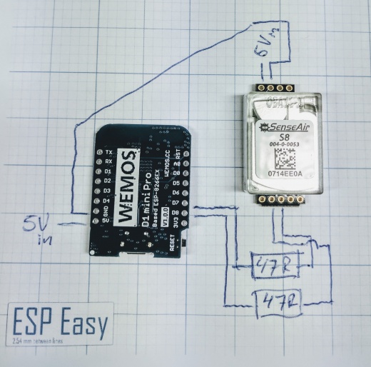
This template is using the standard PCB module of 2.54mm (0.1") between the lines. You can use the template to draw simple schematics and/or connections to help others when you explain your design. As with the other examples that use dimensions you need to print the page as "true size". | This template is using the standard PCB module of 2.54mm (0.1") between the lines. You can use the template to draw simple schematics and/or connections to help others when you explain your design. As with the other examples that use dimensions you need to print the page as "true size". | ||
[https://www.letscontrolit.com/wiki/images/7/7c/ESP_Easy_2.54mm_A4.pdf Download the PDF file] | [https://www.letscontrolit.com/wiki/images/7/7c/ESP_Easy_2.54mm_A4.pdf Download the PDF file] | ||
| + | |||
| + | == Logo == | ||
| + | [[File:ESPeasyLOGO.png|520px]] | ||
| + | |||
| + | Here's a PNG version of the logo. You may also download it as PDF. | ||
| + | |||
| + | [https://www.letscontrolit.com/wiki/images/f/f8/ESPeasyLOGO.pdf Download the PDF file] | ||
| + | |||
| + | ---- | ||
| + | |||
| + | [[File:ESPeasyLOGOblack.png|520px]] | ||
| + | |||
| + | Black PNG version of the logo (with no extra text, used for PCB design). | ||
| + | |||
| + | [https://www.letscontrolit.com/wiki/images/b/b9/ESPeasyLOGOblack.pdf Download the PDF file] | ||
Latest revision as of 15:51, 17 August 2017
Here you find different template files to use in your building or customization process.
Paper templates
Templates used to print.
A4 1mm paper
This template is mainly used when taking pictures and/or measuring different units and devices. We officially use this template when documenting (by picture) the devices that we use with the plugins etc. The lines are 1mm apart and the somewhat thicker lines are 5mm apart, the thickest lines are 10mm apart. Please remember to print the page as "true size" in order to maintain these dimensions on the printed paper.
A4 2.54mm (0.1") paper
This template is using the standard PCB module of 2.54mm (0.1") between the lines. You can use the template to draw simple schematics and/or connections to help others when you explain your design. As with the other examples that use dimensions you need to print the page as "true size".
Logo
Here's a PNG version of the logo. You may also download it as PDF.
Black PNG version of the logo (with no extra text, used for PCB design).


