Difference between revisions of "ProMiniExtender"
(→Input) |
|||
| Line 32: | Line 32: | ||
[[File:EasyConfigPME.png]] | [[File:EasyConfigPME.png]] | ||
| − | You then select the portnumber and additional configuration depending on the controller type. For Domoticz, you enter the IDX that was allocated by Domoticz for this virtual switch. | + | You then select the portnumber and additional configuration depending on the controller type. For Domoticz, you enter the IDX that was allocated by Domoticz for this virtual switch. You have to select between using a digital or analog (PWM) port. |
=== Optional settings === | === Optional settings === | ||
Revision as of 15:34, 10 August 2016
Contents
Introduction
The number of GPIO pins on the ESP module can be expanded with a special IO Expander that's build upon a cheap Arduino Pro Mini board. From here we will call it the PME. We will use the PME that provides more pins that can be used as analog and digital input and output.
Each individual pin can be used as either input or output.
Hardware

The PME needs to be connected through the I2C interface. If you run the PME on 3V3, you can connect the I2C bus directly to the ESP module. (Most 5V Pro Mini boards seem to run fine on 3V3, although the official specs tell you that 16MHz will be out of spec on this lower voltage).
If you run the board on 5V, you would need I2C levelshifters to connect the I2C bus to the ESP module.
Connections
Direct connection possible when the Pro Mini runs on 3V3 VCC only!
 PME 		ESP-01
 GND 	 	GND
 VCC    	VCC
 SDA		GPIO 0
 SCL		GPIO 2
Software
ESP Easy
Configuration depends on how you want to use a certain port on this device. Ports are numbered 0 to 13
Input
To have an input port act as an input switch device (just like with the default onboard GPIO pins) you need to edit a ESP Easy task and select the "ProMini Extender" device.
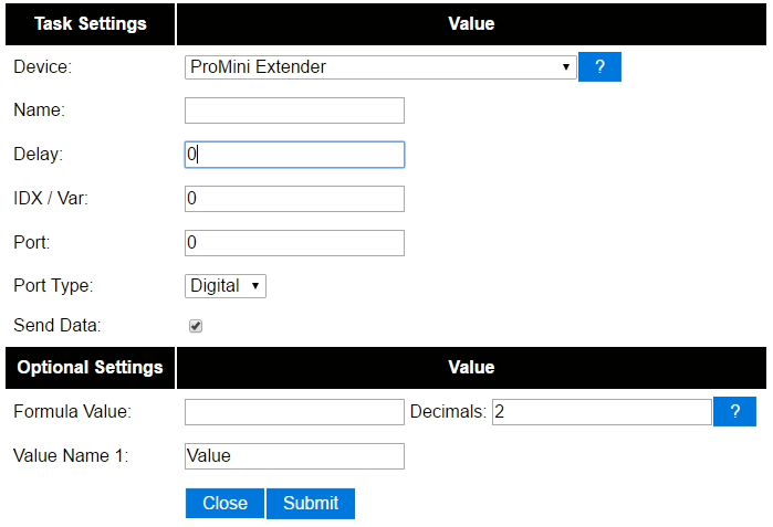

You then select the portnumber and additional configuration depending on the controller type. For Domoticz, you enter the IDX that was allocated by Domoticz for this virtual switch. You have to select between using a digital or analog (PWM) port.
Optional settings
Output
You can control output pins on this chip with the following http command:
http://<ESP IP address>/control?cmd=extgpio,<pin>,0
http://<ESP IP address>/control?cmd=extgpio,<pin>,1