Difference between revisions of "Sonoff Touch"
Jump to navigation
Jump to search
Grovkillen (talk | contribs) m |
Grovkillen (talk | contribs) |
||
| Line 16: | Line 16: | ||
== Wiring/flashing == | == Wiring/flashing == | ||
| + | |||
| + | A programmer is needed to flash this device. | ||
| + | |||
| + | (Progammer -> ESP8285): | ||
| + | |||
| + | 3.3V -> VCC (first via [square] on board) | ||
| + | TX -> RX (second via on board) | ||
| + | RX -> TX (third via on board) | ||
| + | GND -> GND | ||
| + | |||
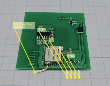
| + | In order to get the ESP8285 in flash mode the GPIO-0 needs to be LOW. (See picture with explanations below.) | ||
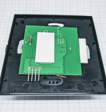
Already soldered board fitted in the casing. | Already soldered board fitted in the casing. | ||
Revision as of 18:13, 19 July 2017
Introduction
Hardware
- ESP chip version: ESP8285
- Flash size: 1M
- Onboard USB-TTL converter: No
- GPIO's broken out/available to free use: None
- GPIO tied to onboard hardware: 0 (button), 12 (Relay 2A@230VAC), 13 (LED blue)
- Power supply information: 90-250VAC
- Antenna: onboard PCB antenna
Wiring/flashing
A programmer is needed to flash this device.
(Progammer -> ESP8285):
3.3V -> VCC (first via [square] on board)
TX -> RX (second via on board)
RX -> TX (third via on board)
GND -> GND
In order to get the ESP8285 in flash mode the GPIO-0 needs to be LOW. (See picture with explanations below.)
Already soldered board fitted in the casing.
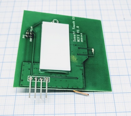
Soldered board seen from front.
Soldered board seen from bottom.
ESP Easy
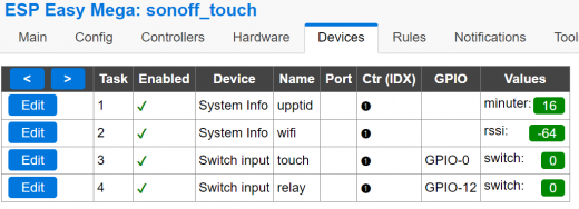
Devices
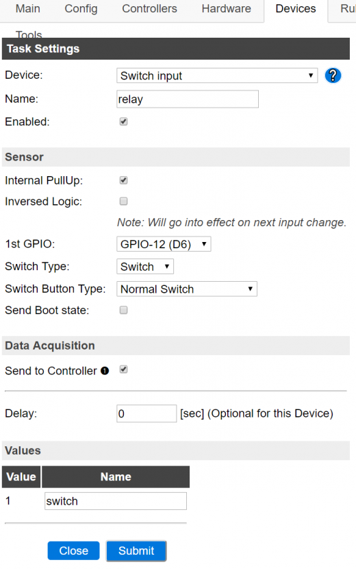
Switch
Relay
