Difference between revisions of "User:Papperone/Module3xRelay"
| Line 4: | Line 4: | ||
I prefer to have bare PCB with my own design which I can populate to the needs, infact I've few of them with 2 or even just one relay assembled. | I prefer to have bare PCB with my own design which I can populate to the needs, infact I've few of them with 2 or even just one relay assembled. | ||
| − | Tinde Store: [https://www.tindie.com/stores/GiovanniCas/] | + | Tinde Store: [https://www.tindie.com/stores/GiovanniCas/] - https://www.tindie.com/stores/GiovanniCas/ |
[[File:3xrelay-1.jpg]] | [[File:3xrelay-1.jpg]] | ||
Revision as of 12:29, 31 March 2018
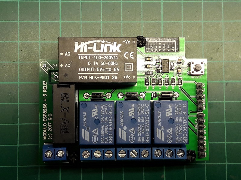
This is a PCB I designed to be able to fit it inside a regular 10x10cm wall connection box. It is meant to be powered by 230VAC and controls up to 3 AC loads; GPIO12/13/14 are used; no LEDs on purpouse to avoid idle consumption and as well they tend to be visible through the standard white plastic covers! on the right I brough out programmin pins, reset button and all avail GPIOs (including ADC with voltage divider to make it 3.3V tolerant). I use this board in my home, mostly to control lights and/or exhausting fans; as well the extra pins I use sometimes to add sensors (temp/hum, light, etc). I prefer to have bare PCB with my own design which I can populate to the needs, infact I've few of them with 2 or even just one relay assembled.
Tinde Store: [1] - https://www.tindie.com/stores/GiovanniCas/
