Difference between revisions of "ESP-01"
Grovkillen (talk | contribs) |
Grovkillen (talk | contribs) |
||
| Line 35: | Line 35: | ||
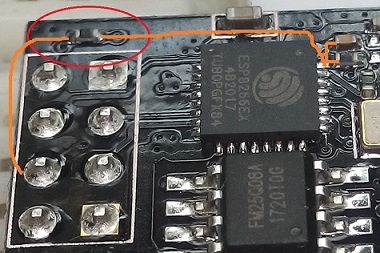
Some users have reported that the reset isn't working on later versions of the ESP-01. There is an additional 6k resistor in the reset line (necessity of this resistor is unknown) between EXT_RSTB and RST pin of 8pins connector. | Some users have reported that the reset isn't working on later versions of the ESP-01. There is an additional 6k resistor in the reset line (necessity of this resistor is unknown) between EXT_RSTB and RST pin of 8pins connector. | ||
| − | After removing and put a jumper back its place, RESET function is working well again. So essentially you just bridge the resistor making it a straight line. | + | After removing and put a jumper back in its place, RESET function is working well again. So essentially you just bridge the resistor making it a straight line. |
[[File:Esp-01 res.jpg|420px]] | [[File:Esp-01 res.jpg|420px]] | ||
Revision as of 21:58, 3 April 2018
Introduction
The ESP-01 is one of the smallest units available. Compared to other ESP units it is powered directly and thus need to be fed with 3.3V and not 5V. Two general GPIOs are available and if you need more you can use the two serial ports (1,3 / RX,TX).
Hardware
- ESP chip version: ESP8266
- Flash size: 1M
- Onboard USB-TTL converter: No
- GPIO's broken out/available to free use: 0, 2
- Power supply information: 3.3VDC
- Antenna: onboard PCB antenna
Wiring/flashing
A programmer is needed to flash this device.
  Programmer     ESP
  TX      <-->   RX
  RX      <-->   TX

  Power
  3.3V    <-->   VDD
  GND     <-->   GND
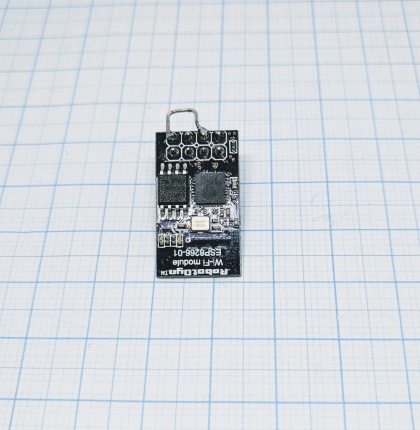
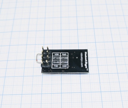
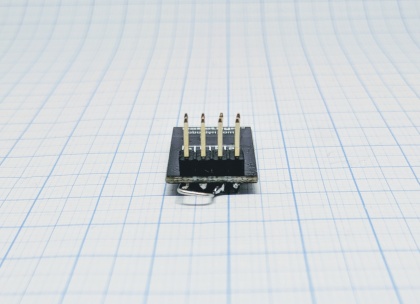
In order to get the unit in flash mode the GPIO-0 needs to be LOW and the CH-EN need to be set to high. The CH-EN can be connected to the VDD, in the pictures a jumper is soldered between these but you could use a resistor to make sure that no over current hurt the unit. Start flashing and do a reset once in order to get the show going.
ESP-01 v3
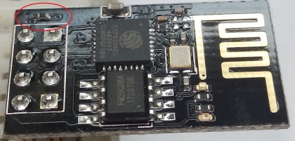
Some users have reported that the reset isn't working on later versions of the ESP-01. There is an additional 6k resistor in the reset line (necessity of this resistor is unknown) between EXT_RSTB and RST pin of 8pins connector. After removing and put a jumper back in its place, RESET function is working well again. So essentially you just bridge the resistor making it a straight line.
The resistor to be bridged.
Orange line shows the connected points for RST.
