ADS1115
Contents
Introduction
The ESP-01 module has no analog input. Only boards like the ESP-07 and ESP-12 break out the single ADC (TOUT) pin on the ESP chip. But we can provide all ESP modules with 4 analog inputs using the ADS1115 I2C ADC chip.
Hardware

The ADS1115 can be bought on eBay as a bare chip or a plug and play module.
ESP Easy
Use the device tab on the ESP Easy webinterface and create a new task by editing one of the available tasks. Select "Analog input - ADS1115" from the dropdown box.
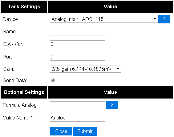

Enter the IDX found in the Domoticz device page. Also select the port on the ADS1115 that you want to read (Numbered 0 - 3). That should be all.
Features found in version 2.0+
Prior to version 2.0+ you could use the ADS1115 to detect four different voltages, one per channel (AIN0 .. AIN3).
Differential values

As of the release of version 2.0.0 you may also use the ADS1115 to measure the differential between two channels. To do this you use the dropdown menu "Input Multiplexer". It works in such a way that you pick the option that you want to calculate the difference between (AnalogX to AnalogY, or AnalogZ to Ground).
Example1:
If AIN0 is measured to be 1.7V and AIN1 is measure to be 1.2V
the value, if the option "AIN0 - AIN1" is set, would be 0.5V.
Example2:
If AIN0 is measured to be 1.7V
the value, if the option "AIN0 - GND" is set, would be 1.7V.
Two point calibration

You may use the two point calibration to adjust the measured value. More information will be added soon.