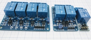
Relais
Introduction
The ESP can control a relay board using one of it's GPIO pins. All relay boards that work with Arduino should also work with the ESP module. Note this is only a possible application of the ESPs ability to send a logic 1/0 (TTL@3.3V) on a GPIO.
Hardware
Connect the relay board to one of the GPIO pins on the ESP module. In case of ESP-01, we will use GPIO-2.It is also possible to connect Relays to I/O I2C port expanders ( PCF8574 + MCP23017 are supported by ESP Easy)
Caution needs to be applied when chosing the GPIO to use. There can be issues on boot as the pins go through defined boot states before taking the state defined under the hardware tab, causing relays to trigger during boot (or reboot which can happen pretty often).
If possible avoid GPIOs 2,3,4,15,16. If the "flicker" during reboot does not matter to your application it is still possible to use the before mentioned GPIO.
Most of the relay boards expect a 5V ttl signal like many arduino boards provide on their output pins. But 3V3 logic should also work.

Design considerations
- Be careful with these relais when you consider to connect them to mains. In that case, some of them are not safe to be used when they are in a circuit with parts that can be touched. For example, if you want to connect such a relay on an ESP that also controls a sensor that can be touched. - The tracks on the pcb are sometime not suitable to carry more than some 4 Amps. See also: http://www.desmith.net/NMdS/Electronics/TraceWidth.html
Software
ESP Easy
Strictly seen, Relays are not a plug-in driven device like most other devices. It is not necessary to have a task (item under Devices tab) for them to work
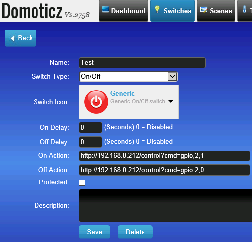
We can control the relay board with two simple http url commands:
http://<ESP IP address>/control?cmd=GPIO,<pin>,0
http://<ESP IP address>/control?cmd=GPIO,<pin>,1
Domoticz example:
ESP Connexio
Syntax: WiredOut 1,On/Off
