Pulse logic input
Contents
Introduction
Just as the ESP may be used with specific pulse counters it may also be used with any generic pulse based unit as long as the pulses are not giving to high voltages. Two examples in this example is a generic water flow sensor and a pulse wheel.
Hardware
Anything that gives a pulse within reasonable voltage levels may be used as input.
Flow sensor
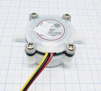
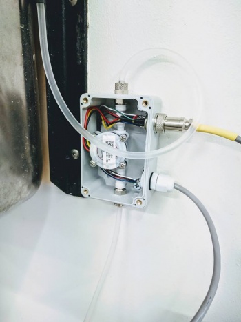
A generic flow sensor that gives a pulse each complete revolution. You may have to measure what each revolution/pulse means in volume.
Pulse wheel, rotary encoders (as simple pulse inputs)
In general: A pulse wheel (generally 100 pulses per rotation) could also work as a input for pulses, good pulse wheels will give the direction of the rotation on different output ports. That means that you will have to use 2 GPIO if you you plan to use that feature (and as of the writing of this text, May 15 2017, a plugin for calculating the phase difference, thus direction, is not in place). Some pulse wheels have 4 outputs, both directions and (for example) 100 pulses per rotation and 25 pulses per rotation. A pulse wheel may be good to use in conjunction with a stepper motor. Smaller pulse wheels are called rotary encoders or digital potentiometers and work pretty much as a real pulse wheel except that they generally do not give the resolution per rotation as a pulse wheel does. They are a lot cheaper though and some also work as a button making them great to use for human interaction with GUI.
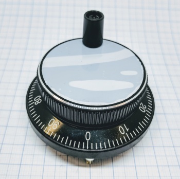
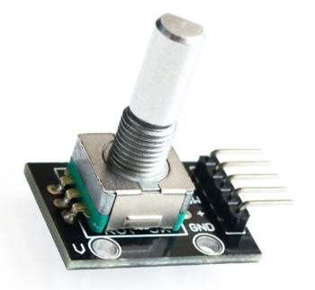
In the context of using a pulse wheel or rotary encoder as a simple pulse input you may only use 1 GPIO and have some other input device tell in which direction the rotation is. A possible example which we will try to cover as soon as possible is to have a rotary encoder with a wheel or cog wheel which is rotated by the wire/chain of a garage door opener (see picture below for simple example). Another example maybe to use the encoder in conjunction with a simple electric motor which opens the curtains. The polarity of the motor gives the direction of the movement.
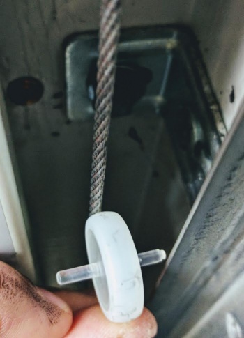
This is just a proof of concept. You would connect the (cog) wheel to the rotary encoder and when the wire/chain is moving the wheel is turned and the encoder would turn as well giving you a simple pulse generator telling you in what position the (for example) garage door or curtain is at.
Software
Within the ESPeasy devices you will have to set up the device using the Pulse Counter type. In the example that follows we use a flow sensor to measure the amount of water that flows out of a system. The delay is set to "5" which equals to five seconds. The GPIO is connected to the pulse output signal cable (in the flow sensor example this cable is yellow). And we have to use the "Debounce Time" in order to filter out some false signals. In this case the debounce is set to 100mSec, please observe that lower debounce time may completely flood your ESP so start from at least 500mSec and work your way down to a good level.
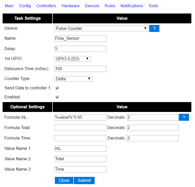
In this example we converted the pulses to mL after measuring 1.5L and divided that volume with the numbers of pulses to reach that volume. This left us with a value of 0.65mL per pulse. Thus the formula for the value was set to "%value%*0.65".
If you use a pulse wheel with 2 or 4 outputs you need to add 1 device for each GPIO.