Rotary Encoder
Jump to navigation
Jump to search
Introduction
A
Hardware
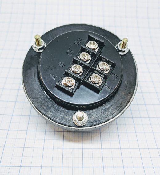
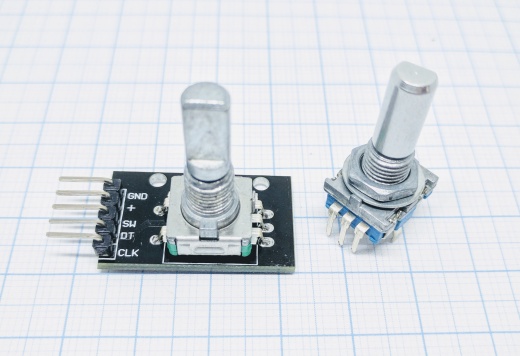
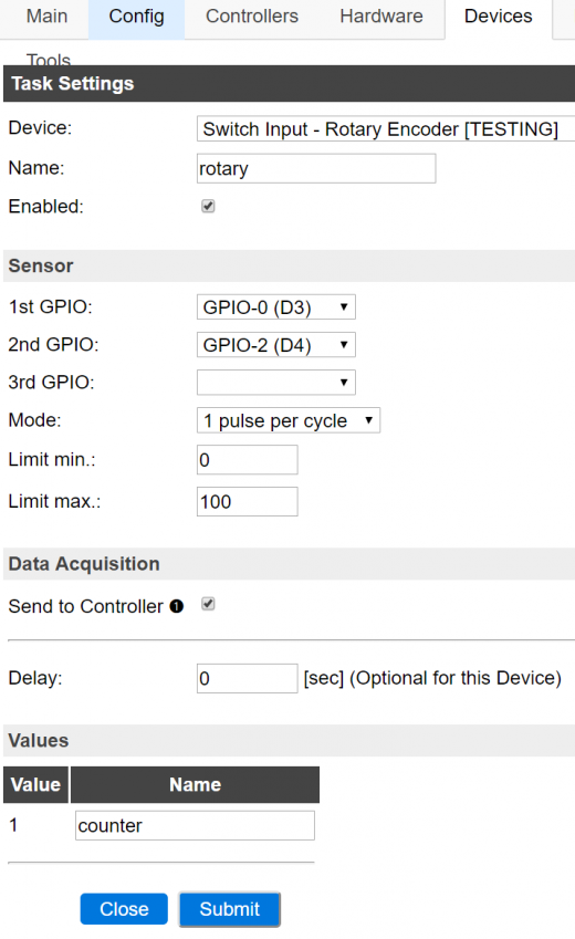
1st-GPIO -> A or CLK on the module (switch A/B if the encoder is counting backwards)
2nd-GPIO -> B or DT on the module (switch A/B if the encoder is counting backwards)
3rd-GPIO -> I on module (OPTIONAL if any available, used to "0" the input after each turn)
3.3V to module VCC
GND to module GND
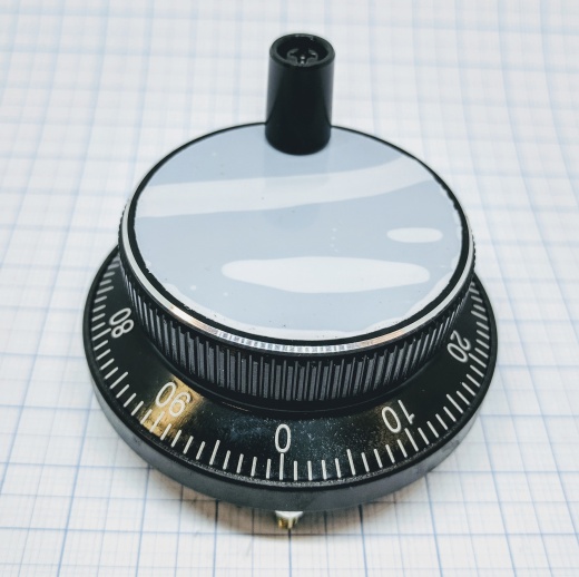
A and B is sometimes labeled CLK and DT, other labels might also be used. Test and see what works for your encoder. If the rotary encoder have A- and B- ports it is ideal to use them since the pulses are negative and doesn't strain the ESP unit's power. Using a positive signal is not a problem though.


