|
|
| (46 intermediate revisions by 4 users not shown) |
| Line 1: |
Line 1: |
| | <!-- BANNER ACROSS TOP OF PAGE --> | | <!-- BANNER ACROSS TOP OF PAGE --> |
| − | {| id="mp-topbanner" style="width:100%; background:#f5faff; margin:1.2em 0 6px 0; border:1px solid CornflowerBlue;" | + | {| id="mp-topbanner" style="width:100%; background:#f5faff; margin:1.2em 0 6px 0; border:1px solid #0077dd;" |
| | | style="width:61%; color:#000;" | | | | style="width:61%; color:#000;" | |
| | | | |
| | {| style="width:280px; border:none; background:none;" | | {| style="width:280px; border:none; background:none;" |
| | | style="width:280px; text-align:center; white-space:nowrap; color:#000;" | | | | style="width:280px; text-align:center; white-space:nowrap; color:#000;" | |
| − | <div style="font-size:162%; border:none; margin:0; padding:.1em; color:#000;">Welcome to [[ESP Easy]],</div> | + | <div style="font-size:162%; border:none; margin:0; padding:.1em; color:#000;">Welcome to [[History of ESP Easy|ESP Easy]],</div> |
| | <div style="top:+0.2em; font-size:95%;">the [https://github.com/letscontrolit open source] firmware for ESP8266.</div> | | <div style="top:+0.2em; font-size:95%;">the [https://github.com/letscontrolit open source] firmware for ESP8266.</div> |
| | |} | | |} |
| Line 12: |
Line 12: |
| | | style="width:18%; font-size:95%;" | | | | style="width:18%; font-size:95%;" | |
| | * [[ESP Hardware|ESP Hardware]] | | * [[ESP Hardware|ESP Hardware]] |
| − | * [[Devices|Devices]] | + | * [[Devices|Supported Sensors/Actuators]] |
| | * [[Modded Hardware|Modded Hardware]] | | * [[Modded Hardware|Modded Hardware]] |
| | | style="width:35%; font-size:95%;" | | | | style="width:35%; font-size:95%;" | |
| − | * [[Forum|Forum]] | + | * [https://www.letscontrolit.com/forum/ Forum] |
| − | * [[Understanding Schematics|Understanding Schematics]] | + | * [[ESP Easy web interface|ESP Easy web interface]] |
| | * [[Template Files|Template Files]] | | * [[Template Files|Template Files]] |
| | | style="width:25%; font-size:95%;" | | | | style="width:25%; font-size:95%;" | |
| | * [[History of ESP Easy|History of ESP Easy]] | | * [[History of ESP Easy|History of ESP Easy]] |
| − | * [[PMilestonesRoadmap|Milestones/Roadmap]] | + | * [[MilestonesRoadmap|Milestones/Roadmap]] |
| | * [[Contributors|Contributors]] | | * [[Contributors|Contributors]] |
| | |} | | |} |
| Line 36: |
Line 36: |
| | | | |
| | <div class="center" style="width: auto; margin-left: auto; margin-right: auto;"> | | <div class="center" style="width: auto; margin-left: auto; margin-right: auto;"> |
| − | <span style="color: white; background:CornflowerBlue">1. Download firmware as binary including flash tool</span> | + | <span style="color: white; background:#0077dd">1. Download firmware as binary including flash tool</span> |
| | <br/>↓<br/> | | <br/>↓<br/> |
| − | <span style="color: white; background:CornflowerBlue">2. Connect the ESP to Windows PC</span> | + | <span style="color: white; background:#0077dd">2. Connect the ESP to Windows PC</span> |
| | <br/><span style="font-size:60%">Using either USB/UART of board or separate USB/TTL adapter</span> | | <br/><span style="font-size:60%">Using either USB/UART of board or separate USB/TTL adapter</span> |
| | <br/>↓<br/> | | <br/>↓<br/> |
| − | <span style="color: white; background:CornflowerBlue">3. Write firmware using flash tool</span> | + | <span style="color: white; background:#0077dd">3. Write firmware using flash tool</span> |
| | <br/><span style="font-size:60%">Note necessity for GPIO to be LOW to enter flashmode</span> | | <br/><span style="font-size:60%">Note necessity for GPIO to be LOW to enter flashmode</span> |
| | <br/>↓<br/> | | <br/>↓<br/> |
| − | <span style="color: white; background:CornflowerBlue">4. Restart ESP. WiFi <nowiki />"AP ESP_0" will appear</span> | + | <span style="color: white; background:#0077dd">4. Restart ESP. WiFi <nowiki />"AP ESP_0" will appear</span> |
| | + | <br/><span style="font-size:60%">If you're not automatically taken to the log-in page, browse to 192.168.4.1</span> |
| | <br/>↓<br/> | | <br/>↓<br/> |
| − | <span style="color: white; background:CornflowerBlue">5. Search for you routers WiFi and connect</span> | + | <span style="color: white; background:#0077dd">5. Search for you routers WiFi and connect</span> |
| | <br/>↓<br/> | | <br/>↓<br/> |
| − | <span style="color: white; background:CornflowerBlue">6. Reconnect to your WiFi and enter IP adress sshown on previous screen</span> | + | <span style="color: white; background:#0077dd">6. Reconnect to your WiFi and enter IP adress shown on previous screen</span> |
| | </div> | | </div> |
| | | | |
| − | = Supported Hardware = | + | = [[ESP_Hardware|Supported Hardware]] = |
| | | | |
| − | ESP Easy can be installed/flashed on nearly every piece of Hardware that has an ESP8266 built-in, newest 2.0.0 version even does support the ESP8285 (basically an ESP8266 with buildtin 1M Flash). Please see the list [[ESP Hardware|here]] for more in depth detail about the hardware. | + | ESP Easy can be installed/flashed on nearly every piece of Hardware that has an ESP8266 built-in, newest 2.0.0 version even does support the ESP8285 (basically an ESP8266 with built-in 1M Flash). Please see the list [[ESP Hardware|here]] for more in depth detail about the hardware. |
| | | | |
| − | = Supported Sensors/Actuators = | + | = [[Devices|Supported Sensors/Actuators]] = |
| | | | |
| − | {| class="wikitable mw-collapsible sortable"
| + | The in depth list of devices (sensors and actuators) is found [[Devices|here]]. |
| − | |+ Long list of devices that has been used and confirmed to work with ESP Easy.
| |
| − | |-
| |
| − | ! Device Type
| |
| − | ! Device Name
| |
| − | ! Physical values measured
| |
| − | ! Power In
| |
| − | ! connection method
| |
| − | ! output format
| |
| − | ! possible I²C addresses
| |
| − | ! level shifter required
| |
| − | ! mounting options
| |
| − | ! Size (LxWxH)
| |
| − | |-
| |
| − | | |
| − | | PulseCounter
| |
| − | | [[File:TCR5000.jpg|thumb|upright=0.5|center|link=TCR5000|[[TCR5000]]]]
| |
| − | | IR emitter + phototransistor (for ex. water/electricity meters), distance
| |
| − | | 3.3V - 5V
| |
| − | | 1 digital GPIO (for pulse/proxy) and/or 1 Analog input (distance)
| |
| − | | binary(0/1) (for pulse/proxy)/ 0-3.3V (distance)
| |
| − | | N/A
| |
| − | | no
| |
| − | | Ø? (1x or 2x)<br/>C-C?
| |
| − | |
| |
| − | |-
| |
| − | | |
| − | | Temperature Sensor
| |
| − | | [[File:DS18b20.jpg|thumb|upright=0.5|center|link=Dallas_DS18b20|[[Dallas_DS18b20 | DS18b20]] ]]
| |
| − | | Temperature (-55 to +125°C)
| |
| − | | 3.3V - 5V
| |
| − | | 1 digital GPIO for multiple sensors
| |
| − | | 1wire bus
| |
| − | | N/A
| |
| − | | no<br/>(yes if you use 5V logic and the ESP unit can't handle that voltage on GPIO)
| |
| − | | None but could be [https://www.letscontrolit.com/wiki/images/5/51/DS18b20_Housing1.jpg placed in] a metal [https://www.letscontrolit.com/wiki/images/6/6d/DS18b20_Housing2.jpg "pipe"/protective sleeve]
| |
| − | | Ø4.6mm x L4.6mm
| |
| − | |-
| |
| − | | |
| − | | Temperature Sensor
| |
| − | | [[File:MLX90614.jpg|thumb|upright=0.5|center|link=MLX90614|[[MLX90614]]]]
| |
| − | | Sensor temperature (-40 to +125°C)
| |
| − | IR temperature (-70 to +380°C)
| |
| − | | 3.3V - 5V
| |
| − | | SDA/SCL or 2 digital GPIO
| |
| − | | I²C bus
| |
| − | | 0x5a
| |
| − | | no
| |
| − | | Ø? (2x)<br/>C-C?
| |
| − | |
| |
| − | |-
| |
| − | | |
| − | | Environment
| |
| − | | [[BMP085_BMP180 | BMP085/BMP180]] [[File:BMP085.png|100px|link=BMP085_BMP180]]
| |
| − | | temperature (-40 to +85°C)
| |
| − | barometric pressure (300-1100 hPa)
| |
| − | | 3.3V
| |
| − | | SDA/SCL or 2 digital GPIO
| |
| − | | I²C bus
| |
| − | | 0x77
| |
| − | | no
| |
| − | | Pins (6x)<br/>C-C2.54mm
| |
| − | |
| |
| − | |-
| |
| − | | |
| − | | Environment | Environment
| |
| − | | [[BME280 | BME280]] [[File:BME280.png|100px|link=BME280]]
| |
| − | | temperature (-40 to +85°C)
| |
| − | humidity ( 0…100 % rel. humidity)
| |
| − | barometric pressure (300-1100 hPa)
| |
| − | | 3.3V
| |
| − | | SDA/SCL or 2 digital GPIO
| |
| − | | I²C bus
| |
| − | | 0x76<br/>0x77
| |
| − | | no
| |
| − | | Ø? (1x)
| |
| − | | 19.0mm x 18.0mm x 3.0mm
| |
| − | |-
| |
| − | | |
| − | | |
| − | | Environment
| |
| − | | [[BMP280 | BMP280]] [[File:BMP280.png|100px|link=BMP280]]
| |
| − | | temperature (-40 to +85°C)
| |
| − | barometric pressure (300-1100 hPa)
| |
| − | | 3.3V
| |
| − | | SDA/SCL or 2 digital GPIO
| |
| − | | I²C bus
| |
| − | | 0x76
| |
| − | | no
| |
| − | | Ø? (2x)<br/>C-C?
| |
| − | | 19.0mm x 18.0mm x 3.0mm
| |
| − | |-
| |
| − | | |
| − | | |
| − | | Environment
| |
| − | | [[MS5611 | MS5611]] [[File:MS5611.png|100px|link=MS5611]]
| |
| − | | temperature (-40 to +85°C)
| |
| − | barometric pressure (10 to 1200 mbar)
| |
| − | | 3.3V
| |
| − | | SDA/SCL or 2 digital GPIO
| |
| − | | I²C bus
| |
| − | | 0x76
| |
| − | | no
| |
| − | | Ø? (2x)<br/>C-C?
| |
| − | | 19.0mm x 18.0mm x 3.0mm
| |
| − | |-
| |
| − | | |
| − | | PulseCounter
| |
| − | | [[LJ12A3]] [[File:LJ12A3-4-Z.jpeg|100px|link=LJ12A3]]
| |
| − | | Inductive proximity sensor
| |
| − | | 5V - 12V
| |
| − | | 1 digital GPIO (for pulse/proxy)
| |
| − | | binary(0/1) (for pulse/proxy)
| |
| − | | N/A
| |
| − | | no<br/>(yes if you consider pull-up and pull-down resistors as level shifter?)
| |
| − | | M12 thread
| |
| − | | Ø12mm x L55mm
| |
| − | |-
| |
| − | | |
| − | | PulseCounter
| |
| − | | [[File:Flow_sensor_pulse.jpg|thumb|upright=0.5|center|link=Pulse logic input|[[Pulse logic input]]]]
| |
| − | | General, output as pulse
| |
| − | | 5V - 12V (in general)
| |
| − | | 1 digital GPIO (for pulse)
| |
| − | | binary(0/1) (for pulse)
| |
| − | | N/A
| |
| − | | no
| |
| − | |
| |
| − | |
| |
| − | |-
| |
| − | | |
| − | | Gas Sensor
| |
| − | | [[File:GP2Y10.jpg|thumb|upright=0.5|center|link=GP2Y10|[[GP2Y10]] ]]
| |
| − | | "Dust" (particle matter: PM2.5)
| |
| − | | 5V
| |
| − | | 1 analog (data) and 1 digital GPIO (for LED)
| |
| − | | analog (for data)
| |
| − | | N/A
| |
| − | | no
| |
| − | | Small flanges on the sides
| |
| − | | 46.0mm x 30.0mm x 17.6mm
| |
| − | |-
| |
| − | | |
| − | | Current
| |
| − | | [[File:INA219.jpg|thumb|upright=0.5|center|link=INA219|[[INA219]] ]]
| |
| − | | Current (max ±3.2A), Voltage (max. 26V)
| |
| − | | 3.3V - 5V
| |
| − | | SDA/SCL or 2 digital GPIO
| |
| − | | I²C bus
| |
| − | | 0x40<br/>0x41<br/>0x44<br/>0x45
| |
| − | | no
| |
| − | | Ø? holes (4x)<br/>C-C??<br/>C-C??
| |
| − | | ?
| |
| − | |-
| |
| − | | |
| − | | Soil moisture
| |
| − | | [["Soil_moisture_sensor" | Soil moisture sensor]] [[File:Soilmoisturesensor_small.jpg|link="Soil_moisture_sensor"]]
| |
| − | | capacitive moisture, temperature, light
| |
| − | | 3.3V - 5V
| |
| − | | SDA/SCL or 2 digital GPIO
| |
| − | | I²C bus
| |
| − | | 0x20 (changeable)
| |
| − | | no
| |
| − | | ?
| |
| − | | ?
| |
| − | |-
| |
| − | | |
| − | | Gas Sensor
| |
| − | | [["CO2_Sensor_MH-Z19" | MH-Z19]] [[File:mh-z19.jpg|100px|link="CO2_Sensor_MH-Z19"]]
| |
| − | | CO2 ppm, temperature, U
| |
| − | | 3.3V
| |
| − | | 2 digital GPIO (Software-Serial)
| |
| − | | serial
| |
| − | | N/A
| |
| − | | no
| |
| − | | Pins (4x + 5x)<br/>C-C2.54mm
| |
| − | | ?
| |
| − | |-
| |
| − | | |
| − | | Light/Lux
| |
| − | | [[BH1750 | BH1750]] [[File:BH1750.jpg|100px|link=BH1750]]
| |
| − | | Illuminance, Lux
| |
| − | | 3.3V
| |
| − | | SDA/SCL
| |
| − | | I²C bus
| |
| − | | 0x5c<br/>0x23
| |
| − | | no
| |
| − | | Ø? holes (2x)<br/>C-C??
| |
| − | | ?
| |
| − | |-
| |
| − | | |
| − | | Light/Lux
| |
| − | | [[TSL2561 | TSL2561]] [[File:TLS2561.png|100px|link=TSL2561]]
| |
| − | | Illuminance, Lux
| |
| − | | 3.3V
| |
| − | | SDA/SCL
| |
| − | | I²C bus
| |
| − | | 0x29<br/>0x39<br/>0x49
| |
| − | | no
| |
| − | | Ø? holes (2x)<br/>C-C??
| |
| − | | ?
| |
| − | |-
| |
| − | | |
| − | | Light/Lux
| |
| − | | [[File:TCS34725-RGB-Color-Sensor.jpg|thumb|upright=0.5|center|link=TCS34725 RGB Color Sensor|[[TCS34725 RGB Color Sensor]]]]
| |
| − | | RGB Color
| |
| − | | 3.3V
| |
| − | | SDA/SCL
| |
| − | | I²C bus
| |
| − | | 0x29
| |
| − | | no
| |
| − | | Ø? holes (2x)<br/>C-C??
| |
| − | | ?
| |
| − | |-
| |
| − | | |
| − | | Light/Lux
| |
| − | | [[File:Photosensitive_resistor.jpg|thumb|upright=0.5|center|link=Photosensitive resistor|[[Photosensitive resistor | Photosensitive resistor]]]]
| |
| − | | Light intensity<br/>Analog 1-100% or Binary above/below trigger value
| |
| − | | 3.3V - 5V
| |
| − | | 1 analog<br/>and/or<br/>1 digital
| |
| − | | analog (0-3.3V)<br/>and/or<br/>binary (0/1)
| |
| − | | N/A
| |
| − | | no
| |
| − | | Ø? hole
| |
| − | | ?
| |
| − | |-
| |
| − | | |
| − | | Environment
| |
| − | | [[File:DHT11.jpg|thumb|upright=0.5|center|link=DHT11_DHT22|[[DHT11_DHT22 | DHT11 (DHT22)]]]]
| |
| − | | temperature (-40 to +85°C)
| |
| − | humidity ( 0…100 % rel. humidity)
| |
| − | | 3.3V - 5V
| |
| − | | 1 digital GPIO for multiple sensors
| |
| − | | 1wire bus
| |
| − | | N/A
| |
| − | | no
| |
| − | | Ø? hole (DHT22)
| |
| − | | ?
| |
| − | |-
| |
| − | | |
| − | | |
| − | | Environment
| |
| − | | [[DHT12 | DHT12]] [[File:DHT12.png|100px|link=DHT12]]
| |
| − | | temperature (-20 to +60°C)
| |
| − | humidity ( 20…95 % rel. humidity)
| |
| − | | 3.3V - 5V
| |
| − | | 1 digital GPIO for multiple sensors
| |
| − | | I²C bus<br/>(or 1wire bus)
| |
| − | | 0xb8
| |
| − | | no
| |
| − | | no
| |
| − | | 12.3mm x 7.5mm x 4.7mm
| |
| − | |-
| |
| − | | |
| − | | Environment | Environment
| |
| − | | [[SI7021/HTU21D| SI7021/HTU21D]] [[File:SI7021.png|100px|link=SI7021/HTU21D]]
| |
| − | | temperature (-40 to +125°C)
| |
| − | humidity ( 0…100 % rel. humidity)
| |
| − | | 3.3V
| |
| − | | SDA/SCL or 2 digital GPIO
| |
| − | | I²C bus
| |
| − | | 0x40
| |
| − | | no
| |
| − | |
| |
| − | |
| |
| − | |-
| |
| − | | |
| − | | Environment | Environment
| |
| − | | [[SHT1X | SHT1X]] [[File:SHT1X.png|100px|link=SHT1X]]
| |
| − | | temperature
| |
| − | humidity
| |
| − | | 3.3V - 5V
| |
| − | | ?
| |
| − | | ?
| |
| − | | ?
| |
| − | | no
| |
| − | |
| |
| − | |
| |
| − | |-
| |
| − | | |
| − | | Environment | Environment
| |
| − | | [[AM2320_i2c_Temperatur_and_Humidity_Sensor | AM2320 ]] [[File:AM2320-Sensor.jpg|100px|link=AM2320_i2c_Temperatur_and_Humidity_Sensor ]]
| |
| − | | temperature (-40 to +80°C)
| |
| − | humidity ( 0…99.9 % rel. humidity)
| |
| − | | 3.3V - 5V
| |
| − | | SDA/SCL or 2 digital GPIO
| |
| − | | I²C bus
| |
| − | | 0x5C (not found via i2c scan?)
| |
| − | | no
| |
| − | |
| |
| − | |
| |
| − | |-
| |
| − | | |
| − | | RFID | RFID
| |
| − | | [[Wiegand-26| Wiegand]] [[File:WiegandRFID_1.jpg|100px|link=Wiegand-26 ]]
| |
| − | | RFID
| |
| − | | 6V - 12V
| |
| − | | 2 digital GPIO
| |
| − | |
| |
| − | |
| |
| − | | yes
| |
| − | |
| |
| − | |
| |
| − | |-
| |
| − | | |
| − | | RFID | RFID
| |
| − | | [[PN532 | PN532]] [[File:PN532.png|100px|link=PN532 ]]
| |
| − | | RFID
| |
| − | | 3.3V
| |
| − | |?
| |
| − | |
| |
| − | |
| |
| − | | no
| |
| − | |
| |
| − | |
| |
| − | |-
| |
| − | | |
| − | |}
| |
| | | | |
| | = OLD Supported Sensors/Actuators List = | | = OLD Supported Sensors/Actuators List = |
| | | | |
| − | {| class="wikitable"
| + | This list is being migrated to the new list found [[Devices|here]]. |
| − | !colspan="2" style="font-size:24px; color:white; background-color: black;"|Sensors (Input)
| |
| − | |-
| |
| − | | |
| − | | |
| − | |style="font-size:16px; color:white; background-color: #0077dd;" align="center"| Distance || style="font-size:16px; color:white; background-color: #0077dd;" align="center"| Switch
| |
| − | |-
| |
| − | | [[DistanceSensor | HC-SR04]] [[File:HC-SR04.jpg|100px|link=]] || [[Switch | Switch]] [[File:Lightswitch.jpg|100px|link=]] [[File:Door Switch.png|100px|link=]] [[File:PIR.jpg|100px|link=]]
| |
| − | |-
| |
| − | | |
| − | |style="font-size:16px; color:white; background-color: #0077dd;" align="center"| Analog || style="font-size:16px; color:white; background-color: #0077dd;" align="center"| More Analog
| |
| − | |-
| |
| − | | [[ Analog | Analog]] [[File:Analog.png|100px|link=]] || [[PCF8591 | PCF8591]] [[File:PCF8591Module.jpg|100px|link=]]<br/>[[ADS1115 | ADS1115]] [[File:ADS1115.jpg|100px|link=]]
| |
| − | |-
| |
| − | | |
| − | |style="font-size:16px; color:white; background-color: #0077dd;" align="center"| Digital inputs || style="font-size:16px; color:white; background-color: #0077dd;" align="center"| Infrared Receivers
| |
| − | |-
| |
| − | | [[MCP23017 | MCP23017]] [[File:MCP23017DIP28.jpg|100px|link=]]<br/>[[PCF8574 | PCF8574]] [[File:PCF8574.jpg|100px|link=]] || [[IR | IR]] [[File:TSOP4838.png|100px|link=]]
| |
| − | |-
| |
| − | | |
| − | | |
| − | | style="font-size:16px; color:white; background-color: #0077dd;" align="center"| Motion
| |
| − | |-
| |
| − | | [[MPU6050 | MPU 6050]] [[File:Mpu-6050.jpg|80px|link=]]
| |
| − | |-
| |
| − | | |
| − | | |
| − | | |
| − | {| class="wikitable"
| |
| − | !colspan="2" style="font-size:24px; color:white; background-color: black;"|Actuators (Output)
| |
| − | |-
| |
| − | |style="font-size:16px; color:white; background-color: #0077dd;" align="center"| Digital output || style="font-size:16px; color:white; background-color: #0077dd;" align="center"| Servo
| |
| − | |-
| |
| − | | [[GPIO | Output pin]] [[File:LED.jpg|100px|link=]]<br/>[[Relais | Relays]] [[File:Relaisbordje.jpg|100px|link=]] || [[Servo | Servo]] [[File:Servo.png|100px|link=]]
| |
| − | |-
| |
| − | |style="font-size:16px; color:white; background-color: #0077dd;" align="center"| IR-Transmit || style="font-size:16px; color:white; background-color: #0077dd;" align="center"| Extra IO
| |
| − | |-
| |
| − | |[[IRTX | IR Led]] [[File:IRLED.png|100px|link=]] || [[MCP23017 | MCP23017]] [[File:MCP23017DIP28.jpg|100px|link=]]<br/>[[PCF8574 | PCF8574]] [[File:PCF8574.jpg|100px|link=]]
| |
| − | |-
| |
| − | |style="font-size:16px; color:white; background-color: #0077dd;" align="center"| PWM || style="font-size:16px; color:white; background-color: #0077dd;" align="center"| Motor Shield
| |
| − | |-
| |
| − | | [[PCA9685 | PCA9685]] [[File:PCA9685Module.jpg|100px|link=]]<br/>[[PWM GPIO| PWM GPIO]][[File:MosFET.png|100px|link=]] || [["Adafruit_Motor_Shield_v2"| Adafruit Motor Shield v2]] [[File:Motor_shield_klein.jpg|100px|link=]]
| |
| − | |-
| |
| − | |style="font-size:16px; color:white; background-color: #0077dd;" align="center"| Buzzer (RTTL) || style="font-size:16px; color:white; background-color: #0077dd;" align="center"|
| |
| − | |-
| |
| − | | [[Buzzer (RTTL) | RTTL]] [[File:buzzer.jpg|100px|link=]]
| |
| − | |}
| |
| − | | |
| | | | |
| | {| class="wikitable" | | {| class="wikitable" |
| Line 435: |
Line 72: |
| | |} | | |} |
| | | | |
| − | = Modded Hardware Products = | + | = [[Modded_Hardware|Modded Hardware Products]] = |
| | | | |
| − | {| class="wikitable sortable"
| + | A list of (officially) modded hardware products is found [[Modded Hardware|here]]. |
| − | |-
| |
| − | ! Device Type
| |
| − | ! Device Name
| |
| − | ! Recommended ESP8266 board
| |
| − | ! Information
| |
| − | |-
| |
| − | | |
| − | | Weather Station
| |
| − | | [[VentusW266 | Ventus W266]] [[File:Ventusw266.png|100px|link=VentusW266]]
| |
| − | | [[WeMos D1 mini]]
| |
| − | | This device is also sold as "RenkForce W205GU".
| |
| − | |-
| |
| − | | |
| − | |}
| |
| | | | |
| | = Tutorials = | | = Tutorials = |
| Line 479: |
Line 102: |
| | * New release candidates are on github: [https://github.com/letscontrolit/ESPEasy/releases ESPEasy version 2.0 and higher] | | * New release candidates are on github: [https://github.com/letscontrolit/ESPEasy/releases ESPEasy version 2.0 and higher] |
| | | | |
| − | [[Tutorial_ESPEasy_Firmware_Upload]] | + | * Connecting and flashing tutorial: [https://www.letscontrolit.com/wiki/index.php/Basics:_Connecting_and_flashing_the_ESP8266] |
| | | | |
| − | = Protocol selection = | + | == 2.0+ firmware on 1MB modules == |
| | | | |
| − | The ESP Easy supports several Home Automation controllers or web-services that collect sensor data.
| + | ''If you are running the stock Mega edition firmware on 1MB modules, you will find that you can no longer load newer images because there's insufficient free space to upload the image (344kB as of 2.0.0.-Dev 9 edition). You can compile smaller images to solve this issue or use a small image that has been build just to upload newer images. So you would always have to use a two-step process to renew using OTA on 1MB modules. Using the uploader image as an in-between step, you can use images up to 604kB.'' |
| | | | |
| − | [[EasyProtocols]] | + | [http://www.letscontrolit.com/downloads/ESPEasyUploaderMega.zip ESPEasyUploaderMega] |
| | | | |
| − | = Configuration =
| + | ''The uploader uses SPIFFS so it uses the same configuration regarding SSID, WPA key and IP. It will connect to your Wifi network as usual, but it will only present this small web page: |
| − | This section tells you more about the ESPeasy setup and the ESP unit's need to know settings (GPIO boot states etc.).
| + | '' |
| | | | |
| − | == GPIO on ESP8266 ==
| + | [[File:ESPUploader.png]] |
| | | | |
| − | {| class="wikitable sortable"
| + | [[Tutorial_ESPEasy_Firmware_Upload]] |
| − | |-
| |
| − | ! GPIO Number
| |
| − | ! GPIO Name
| |
| − | ! Boot State
| |
| − | ! Precautions and information
| |
| − | |-
| |
| − | | 0
| |
| − | | D3
| |
| − | | HIGH for boot<br/>LOW for serial programming
| |
| − | | Pullup resistor on most boards
| |
| − | |-
| |
| − | | 1
| |
| − | |
| |
| − | |
| |
| − | | style="background: orange; black: white;" | Used as serial (TX)<br/>May be used but observe that signal might flicker due to serial activity during boot.
| |
| − | |-
| |
| − | | 2
| |
| − | | D4
| |
| − | | HIGH for boot<br/>HIGH for serial programming
| |
| − | | Connected to onboard LED (low active)<br/>Used as serial1 (TX1)
| |
| − | |-
| |
| − | | 3
| |
| − | |
| |
| − | |
| |
| − | | style="background: orange; black: white;" | Used as serial (RX)<br/>May be used but observe that signal might flicker due to serial activity during boot.
| |
| − | |-
| |
| − | | 4
| |
| − | | D2
| |
| − | |
| |
| − | | Generally used as SDA (I2C)
| |
| − | |-
| |
| − | | 5
| |
| − | | D1
| |
| − | |
| |
| − | | Generally used as SCL (I2C)
| |
| − | |-
| |
| − | | 6
| |
| − | |
| |
| − | |
| |
| − | | style="background: red; color: white;" | Do not use!<br/>Reserved for SPI + flash
| |
| − | |-
| |
| − | | 7
| |
| − | |
| |
| − | |
| |
| − | | style="background: red; color: white;" | Do not use!<br/>Reserved for SPI + flash
| |
| − | |-
| |
| − | | 8
| |
| − | |
| |
| − | |
| |
| − | | style="background: red; color: white;" | Do not use!<br/>Reserved for SPI + flash
| |
| − | |-
| |
| − | | 9
| |
| − | | D11
| |
| − | |
| |
| − | | style="background: red; color: white;" | Do not use!<br/>Reserved for SPI + flash
| |
| − | |-
| |
| − | | 10
| |
| − | | D12
| |
| − | |
| |
| − | | style="background: orange; black: white;" | Use with caution!<br/>Reserved for SPI + flash
| |
| − | |-
| |
| − | | 11
| |
| − | |
| |
| − | |
| |
| − | | style="background: red; color: white;" | Do not use!<br/>Reserved for SPI + flash
| |
| − | |-
| |
| − | | 12
| |
| − | | D6
| |
| − | |
| |
| − | |
| |
| − | |-
| |
| − | | 13
| |
| − | | D7
| |
| − | |
| |
| − | |
| |
| − | |-
| |
| − | | 14
| |
| − | | D5
| |
| − | |
| |
| − | |
| |
| − | |-
| |
| − | | 15
| |
| − | | D8
| |
| − | | LOW for boot
| |
| − | | Pulldown resistor on most boards
| |
| − | |-
| |
| − | | 16
| |
| − | | D0
| |
| − | |
| |
| − | | No PWM. No internal pullup available. Used in sleep mode for wakeup
| |
| − | |-
| |
| | | | |
| − | |} | + | = [[EasyProtocols|Protocol selection]] = |
| | | | |
| − | = ESP Easy web interface =
| + | The ESP Easy supports several Home Automation controllers or web-services that collect sensor data. |
| − | The ESP Easy has a user-friendly web interface for all configuration settings. They are locally stored in flash memory and retained on power-off. | |
| − | We will explain all configuration pages and settings:
| |
| | | | |
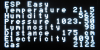
| − | == Main page ==
| + | [[EasyProtocols]] |
| − | URL:<espeasyip><br/>
| |
| − | [[File:ESPEasy_Main.png]] | |
| | | | |
| − | This is an informational page that provides some technical and operational parameters.
| + | = [[Configuration]] = |
| − | The bottom half shows a node list of all known ESP units that are running in your network (this is optional and needs to be configured in tools/advanced) | + | The ESP8266 boards are generally easy to use and understand but some precautions need to be taken when it comes to the different GPIOs available. This [[Configuration|section]] tells you more about the ESPeasy setup and the ESP unit's need to know settings (GPIO boot states etc.). |
| − | The list only shows live systems.
| |
| | | | |
| − | == Config page == | + | = [[ESP Easy web interface|ESP Easy web interface]] = |
| − | URL:<espeasyip>/'''config'''<br/>
| + | The ESP Easy has a user-friendly web interface for all configuration settings. They are locally stored in flash memory and retained on power-off. |
| − | Main settings can be found under "Config" page.
| + | We explain all configuration pages and settings [[ESP Easy web interface|here]]. |
| | | | |
| − | [[File:ESPEasy_Config.png]]
| + | '''<span style="color:red">Do NOT expose the ESP Easy web interface directly to the internet, always make sure that the web interface is only reachable from "trusted/local" networks!</span>''' |
| | | | |
| − | '''Name''' Can be set to an easy to remember name for this system. Can also be used in MQTT communication templates.
| + | = [[ESPEasy Command Reference|Command Reference]] = |
| − | | |
| − | '''Admin Password''' Can be set if you want to protect your system config with a password.
| |
| − | | |
| − | '''SSID''' Wifi network SSID
| |
| − | | |
| − | '''WPA Key''' The key used on your Wifi Access Point
| |
| − | | |
| − | '''WPA AP Mode Key''' The key that ESP Easy will use if it starts as a Wifi Access Point to set the first time configuration
| |
| − | | |
| − | '''Unit nr''' Each ESP Easy unit needs a unique number in the range 1-31. <span style="color:red">This is important for MQTT connections and the Node list! Do not forget to set this field to a non-zero value, not conflicting with other units.</span>
| |
| − | | |
| − | '''Protocol''' Select the protocol for your Home Automation controller or webservice like ThingSpeak.
| |
| − | | |
| − | '''Locate Controller''' You can set the controller based on it's DNS hostname or it's IP address.
| |
| − | | |
| − | '''Controller IP/Hostname''' Set IP or hostname for the controller
| |
| − | | |
| − | '''Controller Port''' Set the TCP port used on your controller or webservice.
| |
| − | | |
| − | '''Sensor Delay''' Set the delay between sensor reporting in seconds.
| |
| − | | |
| − | '''Sleep Mode''' Tick this field to use the ESP in deepsleep mode for low power operation. Read more: [[SleepMode]]
| |
| − | | |
| − | Optional
| |
| − | | |
| − | '''ESP IP''' You can set a static IP for this ESP unit. Set to 0.0.0.0 to use DHCP
| |
| − | | |
| − | '''ESP GW''' If using a static IP, enter the gateway (not needed if no connection to internet is needed!)
| |
| − | | |
| − | '''ESP Subnet''' Enter the local used subnet, usually 255.255.255.0
| |
| − | | |
| − | '''ESP DNS''' Enter you local DNS server IP address. Usually the IP of your local internet router.
| |
| − | | |
| − | == Controllers page (version 2.0+) ==
| |
| − | URL:<espeasyip>/'''controllers'''<br/>
| |
| − | [[File:WebGUI_controllers.PNG]]
| |
| − | | |
| − | It is possible to have multiple controllers/brokers activated.
| |
| − | | |
| − | == Hardware page ==
| |
| − | URL:<espeasyip>/'''hardware'''<br/>
| |
| − | [[File:ESPEasy_Hardware.png]]
| |
| − | | |
| − | '''Status LED''' (version 2.0 only) Select the data pin used for a low active LED to show the status of the firmware. Use D4 (GPIO2) for the on-board blue LED.
| |
| − | | |
| − | [[File:StatusLEDModes.png|200px]]
| |
| − | | |
| − | '''SDA''' Select the data pin used for I2C communications.
| |
| − | | |
| − | '''SCL''' Select the clock pin used for I2C communications.
| |
| − | | |
| − | '''Pin mode x''' Select an optional boot state for this pin, either output low or high
| |
| − | | |
| − | I2C is a well known standard to let multiple devices communicate over just two wires (and ground). We use it to connect sensors to ESP Easy. You can connect multiple sensors to the same two wires. Don't forget to use pull-up resistors on both SDA and SCL, unless one of your sensors already has them mounted on board.
| |
| − | | |
| − | == Rules page ==
| |
| − | URL:<espeasyip>/'''rules'''<br/>
| |
| − | [[File:WebGUI_rules.PNG]]
| |
| − | Here's where the rules goes.
| |
| − | | |
| − | == Notifications page (version 2.0+) ==
| |
| − | URL:<espeasyip>/'''notifications'''<br/>
| |
| − | [[File:WebGUI_notifications.PNG]]
| |
| − | | |
| − | It is possible to have the ESP unit send emails or giving you notifications using a buzzer.
| |
| − | | |
| − | == Devices page ==
| |
| − | URL:<espeasyip>/'''devices'''<br/>
| |
| − | [[File:ESPEasy_Devices.png]]
| |
| − | | |
| − | This is a list of tasks that the ESP Easy will perform. A sensor needs to be defined here to get the values send to your controller.
| |
| − | | |
| − | After selecting a new device, press the ? button to get specific help on this device!
| |
| − | | |
| − | <span style="color:red">Most common mistake if your values remain 0: The ESP Easy mainly targets Domoticz and the internal framework is entirely build upon the IDX field. This needs to match Domoticz. If you run a different protocol, it can be any value but must be non-zero. Just choose '1' in those cases...</span>
| |
| − | | |
| − | == Tools page ==
| |
| − | URL:<espeasyip>/'''tools'''<br/>
| |
| − | [[File:ESPEasy_Tools.png]]
| |
| − | | |
| − | Some maintenance tools.
| |
| − | | |
| − | | |
| − | === Tools Log page ===
| |
| − | URL:<espeasyip>/'''log'''<br/>
| |
| − | [[File:WebGUI_log.PNG]]
| |
| − | | |
| − | This page can be used for debugging issues. The debug level is set to '2' by default and will show sensor readings. Debugging levels can be changed under Tools/Advanced.
| |
| − | | |
| − | If your system runs fine, you can set the level to '0' to turn of logging. This will save valuable RAM!
| |
| − | | |
| − | === Tools Advanced page ===
| |
| − | URL:<espeasyip>/'''advanced'''<br/>
| |
| − | [[File:ESPEasy_Tools_Advanced.png]]
| |
| − | | |
| − | '''Subscribe Template''' Used for MQTT subscription. Selecting a MQTT protocol will automatically fill this field
| |
| − | | |
| − | '''Publish Template''' Used for MQTT publishing. Selecting a MQTT protocol will automatically fill this field
| |
| − | It is also used for the Generic HTTP protocol. Create your custom template here.
| |
| − | | |
| − | '''MQTT Retain Msg'''
| |
| − | | |
| − | '''Message Delay''' To prevent overloading your controller or webservice, a delay between reports can be set. Defaults to 1000 milliseconds. <span style="color:red">For ThingSpeak, you need to set this to 15000! to have multiple sensor readings working</span>
| |
| − | | |
| − | '''Fixed IP Octet''' Special network config where the ESP starts with DHCP to get the basic network config and then sets the last octet to a fixed IP.
| |
| − | | |
| − | '''Use NTP''' To enable internal software clock, synchronized using internet time.
| |
| − | | |
| − | '''NTP Hostname''' Can be left empty as it defaults to pool.ntp.org. Can be changed here if needed.
| |
| − | | |
| − | '''Timezone Offset''' Offset in minutes to GMT. In the Netherlands this should be '60'
| |
| − | | |
| − | '''DST''' Daylight Saving Time. Must be set manually when DST is active to adjust the time.
| |
| − | | |
| − | '''Syslog IP''' Enter your syslog server IP if you have one running and want to debug something.
| |
| − | | |
| − | '''Syslog level''' Level of log messaging to the syslog server. Can be set between 0 - 4 (0=no logging, 1=error, 2=error+info, 3=error+info+debug, 4=error+info+more debug)
| |
| − | | |
| − | '''UDP port''' This is used for communication between ESP unit's. 65500 is just a sample. Use a number that does not conflict with other systems on your network as the ESP uses broadcast messages.
| |
| − | <span style="color:red">If you have a syslog server running, do not enter 514 here!</span>. This fields needs to be non-zero to have the node list running.
| |
| − | | |
| − | '''Enable Serial Port''' Enable/disable the serial port.
| |
| − | | |
| − | '''Serial log level''' Level of log messaging to the serial port. Can be set between 0 - 4 (0=no logging, 1=error, 2=error+info, 3=error+info+debug, 4=error+info+more debug)
| |
| − | | |
| − | '''Web log level''' Level of log messaging to the web gui. Can be set between 0 - 4 (0=no logging, 1=error, 2=error+info, 3=error+info+debug, 4=error+info+more debug)
| |
| − | | |
| − | '''Baud Rate''' Serial port baud rate
| |
| − | | |
| − | '''WD I2C Address''' I2C address to send watchdog messages to. Experimental feature to feed a ATTiny based external watchdog.
| |
| − | | |
| − | '''Custom CSS''' Tick this box to use a custom CSS (style sheet). You must first upload a "esp.css" file one to use this.
| |
| − | <span style="color:red">The CSS filesize can not exceed 4 kbyte!</span>.
| |
| − | | |
| − | '''Use SSDP''' SSDP is a network protocol based on the Internet Protocol Suite for advertisement and discovery of network services and presence information. This option toggles this service.
| |
| − | | |
| − | '''Rules''' Tick this checkbox to enable the Rules section for scripting the device. Else the rules aren't visible and editable and won't be processed at all.
| |
| − | | |
| − | '''I2C ClockStrechLimit'''
| |
| − | | |
| − | '''Global Sync'''
| |
| − | | |
| − | === Tools Wifi scan ===
| |
| − | URL:<espeasyip>/'''wifiscanner'''<br/>
| |
| − | [[File:WebGUI_wifiscanner.PNG]]
| |
| − | | |
| − | Here's a list of all accessible wifi networks and their signal strength.
| |
| − | | |
| − | === Tools I2C scan ===
| |
| − | URL:<espeasyip>/'''i2cscanner'''<br/>
| |
| − | [[File:WebGUI_i2cscanner.PNG]]
| |
| − | | |
| − | If one or more I2C devices are connected to the ESP Easy, you can use this scan feature to verify if devices can be located using their I2C address. If no device is shown, you likely made a mistake on wiring or the I2C configuration in the Hardware page.
| |
| − | | |
| − | If the I2C scanner lists an address, it will also list some well known devices that are fixed or typically found on that address. It does NOT mean that the detected device is verified to work in any way. I2C devices use a 7 bit address and the ESP will just scan all 127 possible addresses. If a device listens to some address it will acknowledge this to the ESP. It does not report the type of device so the ESP can only tell that something is listening!
| |
| − | | |
| − | === Tools Settings up/download ===
| |
| − | URL:<espeasyip>/'''upload''' (for uploading settings)<br/>
| |
| − | [[File:WebGUI_upload.PNG]]
| |
| − | | |
| − | URL:<espeasyip>/'''download''' (for downloading settings, not a webpage but a direct download)<br/>
| |
| − | [[File:WebGUI_download.PNG]]
| |
| − | | |
| − | The ESP Easy settings can be saved to your computer so you can restore them if they are lost or you just want to restore them after some experimenting. You can also upload a custom style sheet.
| |
| − | | |
| − | The system recognizes only two filenames:
| |
| − | | |
| − | '''config.txt'''
| |
| − | | |
| − | This file contains the ESP main configuration settings, except security data. The filesize should be 32k.
| |
| − | You can exchange this file with other people if you like, because WPA keys and config password are not stored into this file.
| |
| − | | |
| − | Security data cannot be saved or restored from file!
| |
| − | | |
| − | | |
| − | '''esp.css''' (Custom Style Sheet, max 4 kb !)
| |
| − | | |
| − | If you want to customize the web gui you can upload (a small) css file. Remember that the webgui is only there for configuration so customization is limited. You may use the following stylesheet as an working example or template for further customization. And don't forget to activate the uploaded stylesheet in the TOOLS>ADVANCED section by enabling the "Custom CSS" option.
| |
| − | | |
| − | <pre style="margin:0%;20%;">
| |
| − | * {
| |
| − | font-family: verdana,sans-serif;
| |
| − | font-size: 13px;
| |
| − | }
| |
| − | h1 {
| |
| − | color: black;
| |
| − | font-size: 16pt;
| |
| − | }
| |
| − | | |
| − | h1::after {
| |
| − | content: " (Powersocket Livingroom)"; /* Give your Device an additional selfexplaing name after the topmost headline */
| |
| − | }
| |
| − | | |
| − | h6 {
| |
| − | color: black;
| |
| − | font-size: 10pt;
| |
| − | text-align: center;
| |
| − | }
| |
| − | .button-menu {
| |
| − | background: #3498db;
| |
| − | background-image: -webkit-linear-gradient(top, #3498db, #2980b9);
| |
| − | background-image: -moz-linear-gradient(top, #3498db, #2980b9);
| |
| − | background-image: -ms-linear-gradient(top, #3498db, #2980b9);
| |
| − | background-image: -o-linear-gradient(top, #3498db, #2980b9);
| |
| − | background-image: linear-gradient(to bottom, #3498db, #2980b9);
| |
| − | -webkit-border-radius: 7;
| |
| − | -moz-border-radius: 7;
| |
| − | border-radius: 7px;
| |
| − | color: #ffffff;
| |
| − | padding: 3px 10px 3px 10px;
| |
| − | border: solid #1f628d 1px;
| |
| − | text-decoration: none;
| |
| − | margin:0px 2px;
| |
| − | }
| |
| − | | |
| − | .button-menu:hover {
| |
| − | background: #8fd4ff;
| |
| − | background-image: -webkit-linear-gradient(top, #8fd4ff, #3498db);
| |
| − | background-image: -moz-linear-gradient(top, #8fd4ff, #3498db);
| |
| − | background-image: -ms-linear-gradient(top, #8fd4ff, #3498db);
| |
| − | background-image: -o-linear-gradient(top, #8fd4ff, #3498db);
| |
| − | background-image: linear-gradient(to bottom, #8fd4ff, #3498db);
| |
| − | text-decoration: none;
| |
| − | margin:0px 2px;
| |
| − | }
| |
| − | | |
| − | .button-link {
| |
| − | border: 1px solid;
| |
| − | border-radius: 5px;
| |
| − | background:ButtonFace;
| |
| − | color:ButtonText;
| |
| − | border-color:ButtonHighlight ButtonShadow ButtonShadow ButtonHighlight;
| |
| − | padding: 5px 15px;
| |
| − | text-decoration: none;
| |
| − | }
| |
| − | .button-link:hover {
| |
| − | background-color:Highlight;
| |
| − | color:HighlightText;
| |
| − | }
| |
| − | .button-link:active {
| |
| − | border-color:ButtonShadow ButtonHighlight ButtonHighlight ButtonShadow;
| |
| − | }
| |
| − | th {
| |
| − | background-color: #369;
| |
| − | color: #ffffff;
| |
| − | padding: 10px;
| |
| − | }
| |
| − | td {
| |
| − | padding: 7px;
| |
| − | }
| |
| − | table {
| |
| − | color: black;
| |
| − | border-collapse:collapse;
| |
| − | }
| |
| − | .div_l {
| |
| − | float: left;
| |
| − | }
| |
| − | .div_r {
| |
| − | background-color: #080;
| |
| − | border-radius: 7px;
| |
| − | color: white;
| |
| − | float: right;
| |
| − | margin: 2px;
| |
| − | padding: 1px 10px;
| |
| − | }
| |
| − | .div_br {
| |
| − | clear: both;
| |
| − | }
| |
| − | | |
| − | </pre>
| |
| − | | |
| − | === Tools Firmware update using OTA ===
| |
| − | URL:<espeasyip>/'''update'''<br/>
| |
| − | [[File:WebGUI_update.PNG]]
| |
| − | | |
| − | Once your first ESP Easy firmware is loaded using the serial interface, subsequent updates can be loaded using the Wifi connection (if your unit has 1MB flash or more!).
| |
| − | More details on OTA firmware update: [[EasyOTA]]
| |
| − | | |
| − | === Tools File List (version 2.0+) ===
| |
| − | URL:<espeasyip>/'''filelist'''<br/>
| |
| − | [[File:WebGUI_filelist.PNG]]
| |
| − | | |
| − | Access to the ESP's files. Possible to download for backup, or upload your own files.
| |
| − | | |
| − | === Tools SD CARD File List (version 2.0+) ===
| |
| − | URL:<espeasyip>/'''SDfilelist'''<br/>
| |
| − | [[File:WebGUI_SDfilelist.PNG]]
| |
| − | | |
| − | Access to the ESP's files stored on the SD card (if any SD card). Possible to download for backup, or upload your own files.
| |
| − | | |
| − | == JSON page (hidden prior to version 2.0+) ==
| |
| − | URL:<espeasyip>/'''json'''<br/>
| |
| − | [[File:WebGUI_json.PNG]]
| |
| − | | |
| − | If you want to get the ESP units variables in a JSON package this is where you want to go. The page is not accessible through any webpage button like the other pages.
| |
| − | | |
| − | = Command Reference =
| |
| | | | |
| | [[ESPEasy Command Reference]] | | [[ESPEasy Command Reference]] |
| | | | |
| − | = System variables Reference = | + | = [[ESPEasy System Variables|System variables Reference]] = |
| | | | |
| | [[ESPEasy System Variables]] | | [[ESPEasy System Variables]] |
| | | | |
| − | = Tutorial Rules = | + | = [[Tutorial Rules|Tutorial Rules]]= |
| − | [[Tutorial Rules]]
| + | Most information on rules (=local logic on ESP without controller) can be found in the tutorials. Rules are a great way of tweaking the ESP Easy firmware to do exactly what you want without the need to tinker with any source code. |
| | | | |
| − | Most information on rules (=local logic on ESP without controller) can be found in the tutorial
| + | More on how is found on the [[Tutorial Rules]] page. |
| | | | |
| | = Support and discussion = | | = Support and discussion = |
| Line 932: |
Line 162: |
| | * Then you're ready for: [[Tutorial building and uploading with platformio]] | | * Then you're ready for: [[Tutorial building and uploading with platformio]] |
| | * And eventually, if you did the github stuff: [[Tutorial Contributing Back To ESPEasy]] | | * And eventually, if you did the github stuff: [[Tutorial Contributing Back To ESPEasy]] |
| | + | |
| | + | = Hardware page = |
| | + | <span style="color: red>For older versions, the Hardware page has now moved to:</span> [[ESP Easy web interface#Hardware page]]! |