Difference between revisions of "Switch"
| (8 intermediate revisions by 2 users not shown) | |||
| Line 1: | Line 1: | ||
| − | = | + | = Introduction = |
| + | The Switch module can read an GPIO-Pin as an Digital Input --> Determine if the pin is connected to ground or not/ The TTL-level of a given Digital device (for example the cheap PIR-Modules HC-SR501, the digital output of an LM393-IC often found on moisture/rain/sound-sensor-modules) | ||
| + | |||
The ESP module can read a basic switch to send a state or dimmer value to your controller. | The ESP module can read a basic switch to send a state or dimmer value to your controller. | ||
| Line 5: | Line 7: | ||
== Hardware == | == Hardware == | ||
| − | Connext a switch between ground and the GPIO pin. | + | Connext a switch between ground and the GPIO pin. On TTL-Level devices, just connect the Digital output of the sensor module to the GPIO (they also need VCC and GND) |
---- | ---- | ||
[[File:Lightswitch.jpg|320px]] | [[File:Lightswitch.jpg|320px]] | ||
---- | ---- | ||
| + | |||
| + | When using the PIR widely available from ebay/ali/amazon, the internal pull-up Resistor doesn't seem to work (and the device doesnt have a proper one either). In order to avoid completly chaotic behaviour (false positives) it is advisable to connect an external pull-up-Resistor between the GPIO and VCC (10KOhm). | ||
| + | |||
| + | [[File:PIR.jpg|320px]] | ||
= Software = | = Software = | ||
| − | + | The switch device can also be used to monitor the output of a GPIO-Pin (used for example to control a Relay). This can be useful when GPIOs are switched by both the controller and the local rules of ESP Easy | |
== Custom Sketch == | == Custom Sketch == | ||
| Line 20: | Line 26: | ||
[[File:EasyConfigSwitch.png]] | [[File:EasyConfigSwitch.png]] | ||
| − | Enter the IDX found in the Domoticz device page. Also select the GPIO pin that you have used to connect the switch device. That should be all for a default switch. | + | Enter the IDX found in the Domoticz device page. Also select the GPIO pin that you have used to connect the switch device. The function of the pull-up is to activate the internal pull-up Resistor of the ESP. A pull-up Resistor connects the GPIO to VCC(=3.3V) through a relativly high Resistor (ie 10KOhm). This makes sure the GPIO reads a stable 1 when not connected to GND (it could float).When using a normal switch or tactile switch, it should be activated. That should be all for a default switch. |
| + | |||
| Line 27: | Line 34: | ||
You can also select between Switch and Dimmer. If you want the ESP Easy to set a fixed dimmer value to the controller, select Dimmer on this dropdown: | You can also select between Switch and Dimmer. If you want the ESP Easy to set a fixed dimmer value to the controller, select Dimmer on this dropdown: | ||
| − | [[File: | + | [[File:EasyConfigSwitchType.png]] |
Click Submit and an additional field will be shown to enter the dimmer set value: | Click Submit and an additional field will be shown to enter the dimmer set value: | ||
| − | [[File: | + | [[File:EasyConfigSwitchDimmer.png]] |
Instead of a conventional state or latching push button, you could also use a momentary push button switch. In this case the ESP Easy will toggle between on/off. | Instead of a conventional state or latching push button, you could also use a momentary push button switch. In this case the ESP Easy will toggle between on/off. | ||
| − | [[File: | + | [[File:EasyConfigSwitchButton.png]] |
| + | |||
| + | Push Button Active Low: Action if input pin tied to ground | ||
| + | |||
| + | Push Button Active HIGH: Action if input pin tied to VCC (3V3) | ||
| + | |||
| + | === Optional settings === | ||
| + | |||
| + | [[ EasyValueNames | Use of value names]] | ||
== ESP Connexio == | == ESP Connexio == | ||
Latest revision as of 22:27, 16 April 2017
Contents
Introduction
The Switch module can read an GPIO-Pin as an Digital Input --> Determine if the pin is connected to ground or not/ The TTL-level of a given Digital device (for example the cheap PIR-Modules HC-SR501, the digital output of an LM393-IC often found on moisture/rain/sound-sensor-modules)
The ESP module can read a basic switch to send a state or dimmer value to your controller.
The input switch needs to be connected to a configurable GPIO on the ESP module.
Hardware
Connext a switch between ground and the GPIO pin. On TTL-Level devices, just connect the Digital output of the sensor module to the GPIO (they also need VCC and GND)

When using the PIR widely available from ebay/ali/amazon, the internal pull-up Resistor doesn't seem to work (and the device doesnt have a proper one either). In order to avoid completly chaotic behaviour (false positives) it is advisable to connect an external pull-up-Resistor between the GPIO and VCC (10KOhm).

Software
The switch device can also be used to monitor the output of a GPIO-Pin (used for example to control a Relay). This can be useful when GPIOs are switched by both the controller and the local rules of ESP Easy
Custom Sketch
ESP Easy
Use the device tab on the ESP Easy webinterface and create a new task by editing one of the available tasks. Select "Switch Input" from the dropdown box.
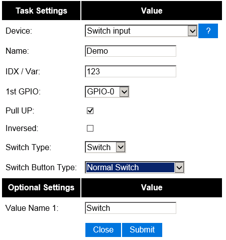

Enter the IDX found in the Domoticz device page. Also select the GPIO pin that you have used to connect the switch device. The function of the pull-up is to activate the internal pull-up Resistor of the ESP. A pull-up Resistor connects the GPIO to VCC(=3.3V) through a relativly high Resistor (ie 10KOhm). This makes sure the GPIO reads a stable 1 when not connected to GND (it could float).When using a normal switch or tactile switch, it should be activated. That should be all for a default switch.
Other settings:
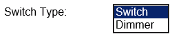
You can also select between Switch and Dimmer. If you want the ESP Easy to set a fixed dimmer value to the controller, select Dimmer on this dropdown:

Click Submit and an additional field will be shown to enter the dimmer set value:
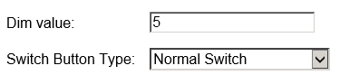

Instead of a conventional state or latching push button, you could also use a momentary push button switch. In this case the ESP Easy will toggle between on/off.


Push Button Active Low: Action if input pin tied to ground
Push Button Active HIGH: Action if input pin tied to VCC (3V3)