Page 1 of 1
Re: HC-SR04+ and wemos d1 mini pro
Posted: 05 Dec 2017, 08:49
by kimot
"Espressif CEO Mr Teo Swee Ann commented that “i can reply officially here: it is 5V tolerant at the IO. while the supply voltage is at 3.3V.”
Page 17 of ESP8266 Datasheet it is mentioned “All digital IO pins are protected from over-voltage” ( 6V )
Of course some serial safety resistors are always very useful ( even with 3.3V - it can damage GPIO too with wrong configuration ), but this is something different than voltage divider.
For example with i2c bus connection is good news, that we do not need voltage converters between 3.3V and 5V.
Re: HC-SR04+ and wemos d1 mini pro
Posted: 05 Dec 2017, 09:42
by grovkillen
kimot wrote: ↑05 Dec 2017, 08:49
"Espressif CEO Mr Teo Swee Ann commented that “i can reply officially here: it is 5V tolerant at the IO. while the supply voltage is at 3.3V.”
Page 17 of ESP8266 Datasheet it is mentioned “All digital IO pins are protected from over-voltage” ( 6V )
Of course some serial safety resistors are always very useful ( even with 3.3V - it can damage GPIO too with wrong configuration ), but this is something different than voltage divider.
For example with i2c bus connection is good news, that we do not need voltage converters between 3.3V and 5V.
A link to that and I'll mention it in the wiki.
Re: HC-SR04+ and wemos d1 mini pro
Posted: 05 Dec 2017, 11:45
by kimot
https://ba0sh1.com/blog/2016/08/03/is-e ... -tolerant/
Page 17 here
https://cdn-shop.adafruit.com/product-f ... N_v4.3.pdf
And I saw some presentation about ESP2866 and spokesman said he talked with director of Espressif about this.
Re: HC-SR04+ and wemos d1 mini pro
Posted: 05 Dec 2017, 12:04
by grovkillen
Re: HC-SR04+ and wemos d1 mini pro
Posted: 05 Dec 2017, 12:53
by Shardan
Please explain what fried several ESP8266 on trying 5V feed here.
Talking to someone who talked to someone is no valid explanation for that.
Re: HC-SR04+ and wemos d1 mini pro
Posted: 05 Dec 2017, 16:34
by kimot
Shardan wrote: ↑05 Dec 2017, 12:53
Please explain what fried several ESP8266 on trying 5V feed here.
Talking to someone who talked to someone is no valid explanation for that.
And datasheet is not valid information?
But better looking for graphs someone measured?
Look again at entire text and graphs:
https://ba0sh1.com/blog/2016/08/03/is-e ... -tolerant/
Of course there is written how you can destroy GPIOs, but in that case it is possible with 3V too.
Re: HC-SR04+ and wemos d1 mini pro
Posted: 05 Dec 2017, 17:49
by Shardan
The Expressif ESP8266 datasheet can be found here:
http://espressif.com/sites/default/file ... eet_en.pdf
For I/O voltage it says for input values Vi:

- ESP8266_Electrical_Characteristics_marked.jpg (492.46 KiB) Viewed 26958 times
Re: HC-SR04+ and wemos d1 mini pro
Posted: 05 Dec 2017, 22:46
by TD-er
Indeed, better strongly advice to run on 3.3V logic levels and maybe mention there is some debate on whether the GPIO's are 5V tolerant.
The average user of these devices is probably not knowledged enough to know the implications, so better safe than sorry.
Re: HC-SR04+ and wemos d1 mini pro
Posted: 06 Dec 2017, 02:04
by grovkillen
TD-er wrote: ↑05 Dec 2017, 22:46
Indeed, better strongly advice to run on 3.3V logic levels and maybe mention there is some debate on whether the GPIO's are 5V tolerant.
The average user of these devices is probably not knowledged enough to know the implications, so better safe than sorry.
Yes, agree. Will try to formulate something in that direction.
Re: HC-SR04+ and wemos d1 mini pro
Posted: 10 Jan 2018, 20:58
by karadn
Now I finaly connect my wemos d1 mini to ultrasonic HC-SR04, but it was not reading distance.
in log I see: 523491 : SR04 : Distance: SR04 : Distance: No reading!
In GPIO-12 I connect Trig, in GPIO-13 I connect Echo

- Capture.PNG (14.25 KiB) Viewed 26730 times
Re: HC-SR04+ and wemos d1 mini pro
Posted: 10 Jan 2018, 22:42
by toffel969
If it is not the "+" version, no surprise. The gpio being 5v tolerant or not, the US needs 5v logic level to drive the speaker to send out a ping
Re: HC-SR04+ and wemos d1 mini pro
Posted: 11 Jan 2018, 07:32
by karadn
It is not + version.
Now I power it from USB port, so what is yours suggestions, how I must power it?
Re: HC-SR04+ and wemos d1 mini pro
Posted: 11 Jan 2018, 10:20
by toffel969
karadn wrote: ↑11 Jan 2018, 07:32
It is not + version.
Now I power it from USB port, so what is yours suggestions, how I must power it?
you need to connect it to the gpio by using a 3,3/5v logiv level converter, all the info is there
check the wiki
https://www.letscontrolit.com/wiki/index.php/HC-SR04
https://www.letscontrolit.com/wiki/inde ... _Converter
My suggestion is to use a 5V power supply and a bidirectional level shifter. They are dead cheap and it works
Re: HC-SR04+ and wemos d1 mini pro
Posted: 11 Jan 2018, 12:58
by Shardan
For some clarification:
The HC-SR04 (old version without "+") definitely needs 5V to work nicely.
Some of them work, some not. Maybe depending on manufacturing tolerances.
Anyways if it works at all the ultrasonic "ping" is very weak so it detects about 30cm max, that's all.
The input ("Trigger") works quite nice with the 3.3V from the ESP.
This can be connected directly to the ESP without problem.
The output signal gives 5V, I'd be carefull with that. Many people tell the ESP is 5V friendly on the inputs...
If it really is or if it just can stand 5V on input for a (short?) while and might die later stays vague.
Whatever people say: The ESP8622 datasheet says inputs are not 5V tolerant and working with 5V at input can't be guaranteed.
Thats an instance I trust far more then an "it works for me" result from a few tests.
Anyways in this case a level shifter is not necessary, two resistors do the job quite well.
For example if using GPIO12, connect a resistor of 2.2 KOhm from GPIO12 to ground.
Connect a resistor of 1 KOhm from the GPIO12 to the output of the HC-SR04.
This works because we just need to lower the level of the output signal from the HC-SR04.
Level-converter are bi-directional so you can send data from low voltage side to high voltage
side and vice versa. Here we just go from "high" to "low" so a passive divider does well.
Regards
Shardan
PS: *Note to myself: Update the HC-SR04 Wiki, it's overdue*
Re: HC-SR04+ and wemos d1 mini pro
Posted: 11 Jan 2018, 14:08
by karadn
Yes I already use two resistors for GPIO12.
I power D1 via USB connector (USB powerbank), ultrasonic sensor VCC pin is connected to D1 5V pin, is this ok or not?
Re: HC-SR04+ and wemos d1 mini pro
Posted: 11 Jan 2018, 14:26
by Shardan
The ultrasonic ping takes some energy, on top i don't know how your power bank behaves.
Most likely there is some electronics for loading and protecting inside the power bank and
it might react to the pulses from the HC-SR04 or not.
I've tested taking the power from the WeMos pin, it should work. Anyways there might be
a diode in serial so you get only 4.3V instead of 5V so not the "full power".
I'd prefer a separate 5V power supply to get a test runing and then going on step by step.
Regards
Shardan
Re: HC-SR04+ and wemos d1 mini pro
Posted: 11 Jan 2018, 15:46
by karadn
Thank you Shardan.
If I use separate 5V power for ultrasonic, how I must connect it, then I connect trig and echo pin only to wemos? Where I must connect ground?
Thank you
Re: HC-SR04+ and wemos d1 mini pro
Posted: 11 Jan 2018, 16:28
by Shardan
Ground is the "common point for all".
So Gnd from WeMos, GND from HC-SR04 and GND from external power supply should be connected.
The "Trigger" of the HC-SR04 can be directly connected to one GPIO.
Output should be connected via resistors as described above to another GPIO.
+5V from Power supply to the Vin (or Vcc) of the HC-SR04.
Then power the WeMos from your power bank as before.
Regards
Shardan
Re: HC-SR04+ and wemos d1 mini pro
Posted: 15 Jan 2018, 18:31
by karadn

- Capture.PNG (16.19 KiB) Viewed 26787 times
Are this settings for GPIO 12 and 13 are ok, or I must set something?
Re: HC-SR04+ and wemos d1 mini pro
Posted: 15 Jan 2018, 18:57
by NDR008
I have a 3.3v version. But couldn't get it to work.
Re: HC-SR04+ and wemos d1 mini pro
Posted: 15 Jan 2018, 19:13
by Shardan
karadn wrote: ↑15 Jan 2018, 18:31
Capture.PNG
Are this settings for GPIO 12 and 13 are ok, or I must set something?
Just leave them untouched - it's OK.
Re: HC-SR04+ and wemos d1 mini pro
Posted: 15 Jan 2018, 19:14
by Shardan
NDR008 wrote: ↑15 Jan 2018, 18:57
I have a 3.3v version. But couldn't get it to work.
Please give some more info.
Re: HC-SR04+ and wemos d1 mini pro
Posted: 16 Jan 2018, 08:49
by NDR008
I will take photo later.
Re: HC-SR04+ and wemos d1 mini pro
Posted: 16 Jan 2018, 11:57
by NDR008
This is the one I had purchased:
https://www.ebay.de/itm/Micro-Mini-3-3- ... 2749.l2649
I cannot describe why it did not work well.
I should try again and document my steps.
I hada LoLin NodeMCU working with a contact switch input and I2C BMP-sensor.
Later I added the ultrasonic thingy and things stopped to work, but it may be a result of my non-linear trial and error.
(It was my first time working with ESP, and I was doubting if I had enough power, and all sorts of factors).
Re: HC-SR04+ and wemos d1 mini pro
Posted: 16 Jan 2018, 14:00
by Shardan
THe nodeMCU's have a voltage regulator 5V -> 3.3V. Usually this is a LM1117-3.3 or an even smaller one.
These regulators can take some current, it should be enough for a HC-SR04.
With the widespread WeMOS D1 Mini it might be near to limits as they use a very small regulator.
Anyways, together with nodeMCU it should work.
Another problem: Powering via USB cable? Try a short and thick cable!
Most cheaper USB cables have wires like a hair... if the HC-SR04 starts sending pulses it might be too much.
Another possible reason:
The US breakout you use is "like HC-SR04" but it obviously uses another circuit inside.
The HC-SR04 has a crystal onboard and another layout, this one has no crystal.
So it is questionable if they are really compatible to eachother.
Re: HC-SR04+ and wemos d1 mini pro
Posted: 16 Jan 2018, 16:11
by NDR008
Yeah, unfortunately the seller contacted me to recommend this one (as I bought the NodeMCU at the same time).
I agree with you on USB cables.
I had my raspberry Pi indicating power issues even though I tried 3 USB power sources including a 3A capable block.
Finally I found the cable was the limiting factor.
1st cable: always caused power problems.
2nd cable: caused occasional problems.
3rd cable: raspberry pi has not once throttled due to power shortage.
Re: HC-SR04+ and wemos d1 mini pro
Posted: 16 Jan 2018, 16:45
by karadn
My sensor HC-SR04 still not working. I try with sepparate power the ultrasonic, but no luck.
Can you please check my connections and settings, now I power Wemos via USB adapter (5V).
- 20180116_163958.jpg (973.34 KiB) Viewed 27079 times

- Capture.PNG (13.76 KiB) Viewed 27079 times
Re: HC-SR04+ and wemos d1 mini pro
Posted: 16 Jan 2018, 18:48
by Shardan
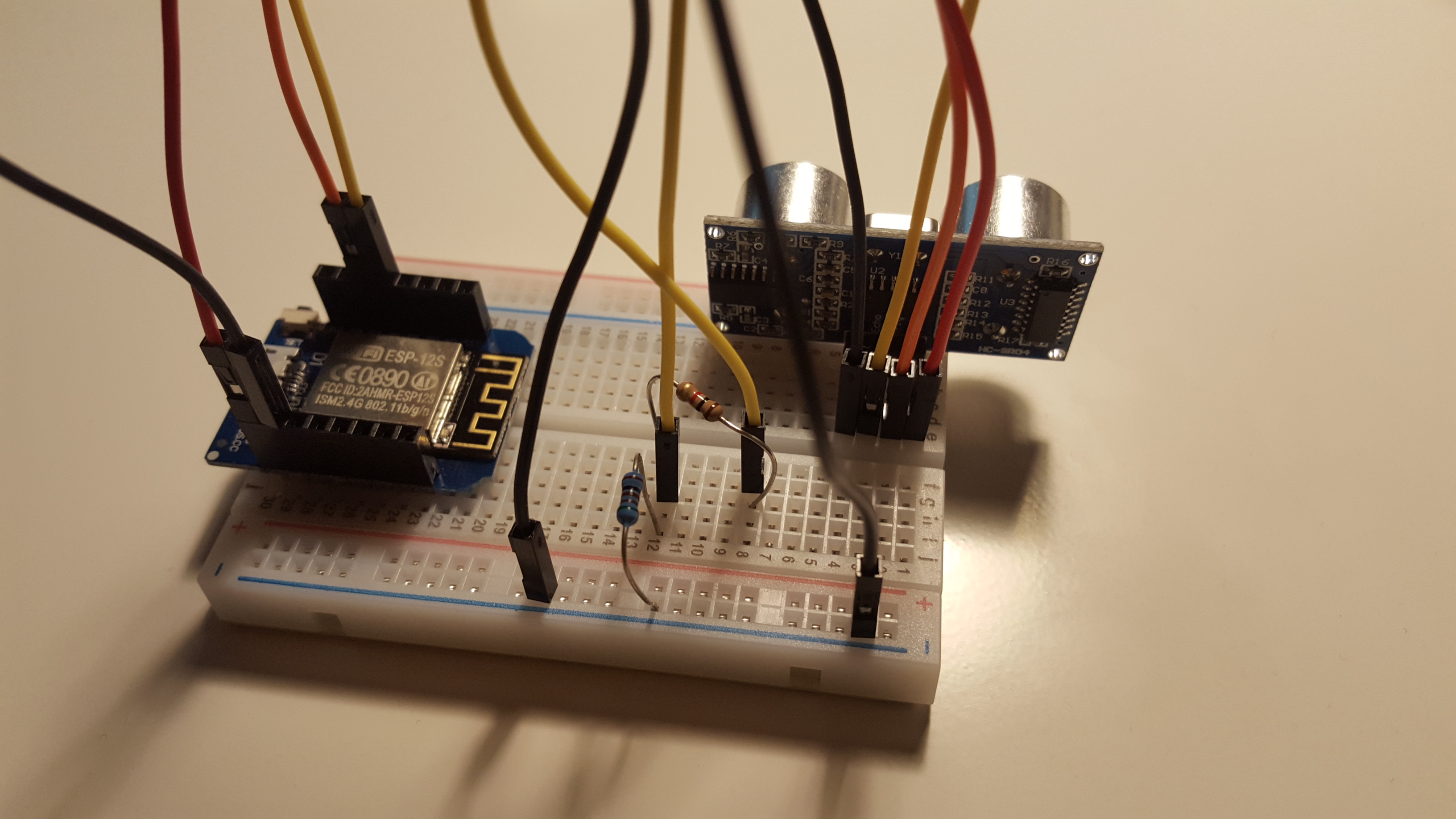
Hm.. looks good to me, as far as i can see.
That was my testing setup:
.

- HC-SR04_on_Breadboard.jpg (460.82 KiB) Viewed 27072 times
.
It's same and worked, powered with a thick USB cable from my computer.
So what to do?
Check all cables first, a digital ohm meter helps a lot.
I've seen alot of these cheap DuPont cables having slack joints or no connection at all.
Breadboards are somewhat susceptible for bad contacts too.
Regards
Shardan
Re: HC-SR04+ and wemos d1 mini pro
Posted: 16 Jan 2018, 19:27
by Shardan
Just for the record:
I've assembled my test setup again, uploaded the actual v2.0-20180116 for testing.
It worked out of the box.
Re: HC-SR04+ and wemos d1 mini pro
Posted: 16 Jan 2018, 21:07
by karadn
So in settings must be:
- 1st GPIO set to GPIO-13, where Trig is connected.
- 2nd GPIO set to GPIO-12, where Echo is connected.
Is that ok?
Re: HC-SR04+ and wemos d1 mini pro
Posted: 16 Jan 2018, 21:13
by Shardan
Yep..
Just it does not hurt if you swap accidentally, the device will just show 0.00.
If you doubt about that, swap the cables for a test.
Re: HC-SR04+ and wemos d1 mini pro
Posted: 17 Jan 2018, 18:54
by karadn
The voltage that come from wemos 5v pin is 4.830V, it seams that is not enough for HC-SR04, because if I separate power 5V to ultrasonic it works now.
Is 4.8V realy too low for this sensor? So I must buy HC-SR04+ or P version?
Re: HC-SR04+ and wemos d1 mini pro
Posted: 17 Jan 2018, 20:13
by Shardan
I didn't have a problem using the 5V from the WeMOS D1 or nodeMCU.
Anyways, the nodeMCU has a diode separating the 5V output from the 5V input from USB.
Diodes have a forward-loss so this might be a problem.
This is difficult to decide without hands-on on your device at a well equipped test site.
It might be a problem of the HC-SR04 itself also, tolerances of parts or something.
These boards are cheapest china made stuff so this might occur.
I'd get some HC-SR-04 from a cheap source like AliExpress and check them out.
5 pieces come around 3,50€ at AliExpress.
Re: HC-SR04+ and wemos d1 mini pro
Posted: 17 Jan 2018, 20:19
by TD-er
karadn wrote: ↑17 Jan 2018, 18:54
The voltage that come from wemos 5v pin is 4.830V, it seams that is not enough for HC-SR04, because if I separate power 5V to ultrasonic it works now.
Is 4.8V realy too low for this sensor? So I must buy HC-SR04+ or P version?
Like Shardan already mentioned. If the wires powering the device are too thin, then the voltage may drop when trying to use more power.
It is then simply a resistor with a voltage drop over the wire which will increase when the current increases.
Re: HC-SR04+ and wemos d1 mini pro
Posted: 17 Jan 2018, 21:27
by karadn
I have 3 sensors and with all is the same. I test sensor also with Wemos D1 pro and also not working.
Re: HC-SR04+ and wemos d1 mini pro
Posted: 17 Jan 2018, 21:43
by Shardan
Then it gets difficult to check what's the reason without hand-on on a test site.
I suspice there is a problem with power supply, but honestly that's applied prophecy.
How do you supply power to the circuit? USB cable and power from PC?