Like I write in another thread I tried yesterday to use a INA219 with one of my ESP8266-01 (1MB). I think I can be surf that my settings are right. Now it seems that it will not work as if the INA219 is not found. And even if I choose only current all three values voltage, current and power are shown.
Has anyone such a combination successful running? I use now the current version of ESPeasy from last night, but the problem is the same with v2.0.0-dev12.
Problem with ESP8266 and INA219?
Moderators: grovkillen, Stuntteam, TD-er
Re: Problem with ESP8266 and INA219?
I tested it with 3 of these to make sure each one could be read independently.
Are you sure they have the address set and to an unique I2C address?
Are SDA and SCL set correct?
Try them without connecting to anything else (e.g. some load you want to measure), just to make sure there is no grounding issue.
Are you sure they have the address set and to an unique I2C address?
Are SDA and SCL set correct?
Try them without connecting to anything else (e.g. some load you want to measure), just to make sure there is no grounding issue.
Re: Problem with ESP8266 and INA219?
It seem to depend somehow on the ground. Now I use the same source for the voltage of the device that I want to measure with another device. More exactly, I use ESP8266-A with INA219 to measure the voltage of ESP8266-B. If I use the same source for the voltage of ESP8266-A for the INA219 it will not work, if I use the voltage of ESP8266-B it works. A little bit strange for me. On the other side this way I can understand how it's possible to measure currency and voltage with one device.
One more question: What is the minimal usable time delay? Is 1s to short for the ESP8266-01?
One more question: What is the minimal usable time delay? Is 1s to short for the ESP8266-01?
Re: Problem with ESP8266 and INA219?
You have to look at how the shunt resistor is connected.
The ground of the ESP and the INA219 should be directly connected, not via the shunt.
Will have to test if 1sec delay is usable.
I still have to look into the scheduling of tasks and maybe a measurement each second may be a little short interval if there are more I2C devices connected.
Other services may also affect performance.
Re: Problem with ESP8266 and INA219?
Thank you for your help.
In this examples that I found the ground of the measured device is always connected to the ground of the measuring-device (in our case the ESP8266-01). Will this not be a problem, because the ground is not always the same level?
http://3egadgets.com/img/cms/Current_Me ... b-1024.jpg
https://www.rototron.info/wp-content/up ... 219_03.jpg
Re: Problem with ESP8266 and INA219?
You are correct. In my memory it was a different schematic.
The shunt is at the + line
So the gnd should be the same for all, as is described very well in the image you linked:
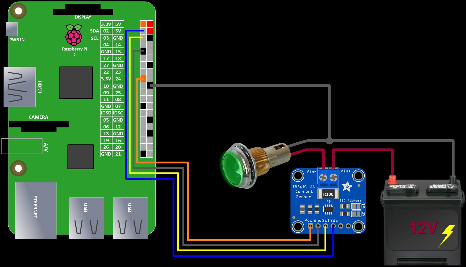
I am not sure what voltage is being measured:
But I guess it should make a difference if the load is connected to V+ or V-. According to the schematic in the image above, the load should be connected to the V-.
And better have a separate GND line to carry all the power of the load you want to measure.
The shunt is at the + line
So the gnd should be the same for all, as is described very well in the image you linked:
I am not sure what voltage is being measured:
- GND => V-
- GND => V+
But I guess it should make a difference if the load is connected to V+ or V-. According to the schematic in the image above, the load should be connected to the V-.
And better have a separate GND line to carry all the power of the load you want to measure.
Who is online
Users browsing this forum: Bing [Bot] and 17 guests