You're using the 5V pin for pull-up.
that's a mistake, because I needed to give power to the flow sensors, I mixed the power and the pull-up!
Another drawing with both separate
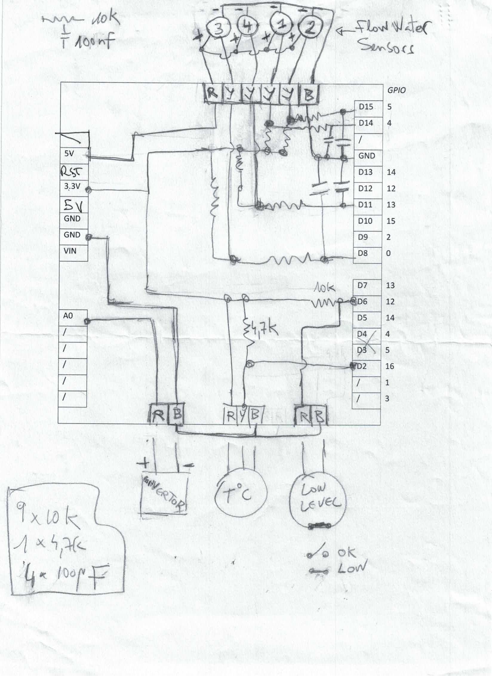
- schema_V1R1.jpg (203.49 KiB) Viewed 8408 times
What this signal is coming from 1...4
something that's connected at the top of the drawing?
These are the flow sensors
https://fr.aliexpress.com/item/32696287 ... 6c37eqxc4Y
The yellow wire is the signal. I've planned to put all the "plus" together and connected to the Wemos 5V and idem for the "minus" to the GND. Perhaps it could have been better to wire the 5V to another power, but I think I need to have the minus to the Wemos GND.
"low level" indicator. I assume it is a switch that is normally closed
I'm not sure to understand the point

It's a float switch like this
https://fr.aliexpress.com/item/40010374 ... 1c104af3-0. I don't have this exact model on hands but I think it is "ok" when opened and "low" when closed (at the present time it is inside my tank, I need to look at it...)
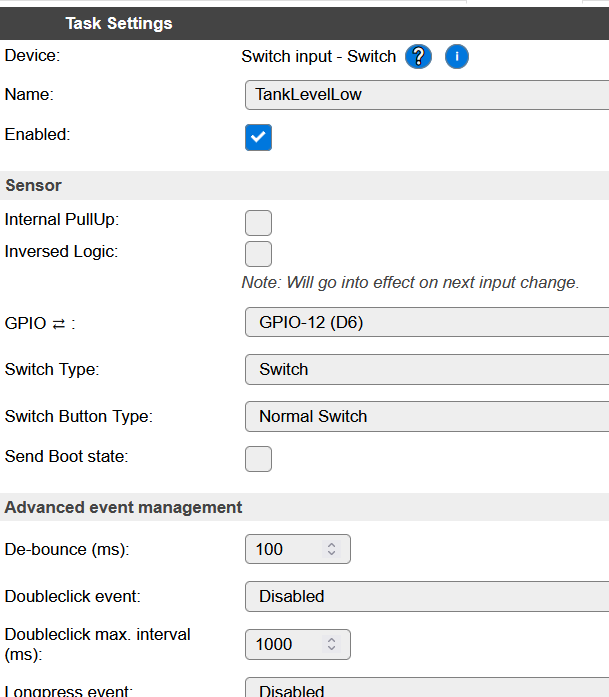
- Screenshot 2021-06-18 154052.png (36.27 KiB) Viewed 8408 times
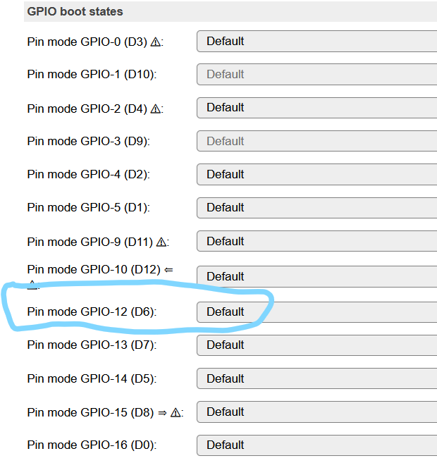
- Screenshot 2021-06-18 160828.png (40.78 KiB) Viewed 8408 times
you are still using GPIO-0, which may be pulled somewhere by "3"
yes. Can I use another GPIO (need to be available ; when testing there was no other solution). Do you have any advise on this?
measure the voltage between each GND and 5V and each GND and 3v3
Done, they are OK