PCF8574 - How does it work ?
Moderators: grovkillen, Stuntteam, TD-er
PCF8574 - How does it work ?
Hello,
use ESP-01 with Build 105
"Devices" Settings are SDA: GPIO-2 / SCL: GPIO-0
"Tools / I2C Scan" the return value are : 0x38
Device Setting :
Device : Switch input - PCF8578
Name: OUTPCF
Delay: 0
IDX/Var: 38
Port: 0
Value Name1: Switch
On the port "0" a LED is connected.
to control the port "0" use the command
http://<ESP IP address>/control?cmd=pcfgpio,0,1
The Return value are : { "log": "GPIO 0 Set to 1", "plugin": 19, "pin": 0, "mode": "output", "state": 1 }
But the port "0" don't worked
has an idea , do not come on
Can you Hellllllppppppppppp
Re: PCF8574 - How does it work ?
Hi,bodyfix wrote:Hello,
use ESP-01 with Build 105
"Devices" Settings are SDA: GPIO-2 / SCL: GPIO-0
"Tools / I2C Scan" the return value are : 0x38
Device Setting :
Device : Switch input - PCF8578
Name: OUTPCF
Delay: 0
IDX/Var: 38
Port: 0
Value Name1: Switch
On the port "0" a LED is connected.
to control the port "0" use the command
http://<ESP IP address>/control?cmd=pcfgpio,0,1
The Return value are : { "log": "GPIO 0 Set to 1", "plugin": 19, "pin": 0, "mode": "output", "state": 1 }
But the port "0" don't worked
has an idea , do not come on
Can you Hellllllppppppppppp
PCFGPIO pin numbering does not begin with 0.
The GPIOs are numbered 1 - 8 not 0 - 7.
Try This instead:
http://<ESP IP address>/control?cmd=pcfgpio,1,1
Re: PCF8574 - How does it work ?
Hello dduley,
Thanks for the note, but it does not work with Port 1
Re: PCF8574 - How does it work ?
Hi Bodyfix,bodyfix wrote:Hello dduley,
Thanks for the note, but it does not work with Port 1
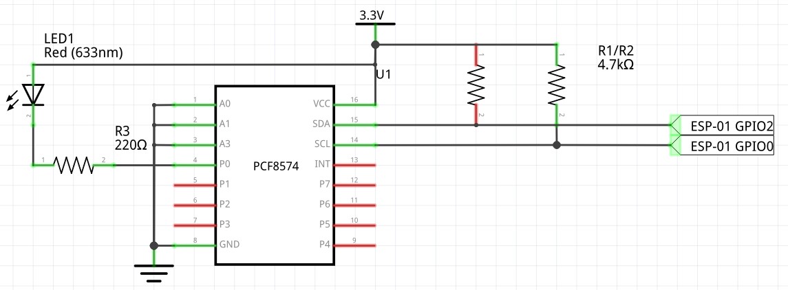
How is your PCF8574 wired up? These things are really open drain output (Even though the data sheet says they are push pull). They really do best when they pull down. This requires an external pullup resistor. What about the addressing of the chip? Pins 1,2 and 3 (A0 - A3) should all be pulled to Gnd. Which version of the chip do you have: the PCF8574 or the PCF8574A?. The two parts differ in the address range they respond to.
Can you put a volt meter on various pins and try other outputs? You may have damaged output 1.
I know...a lot of questions! but I am trying to get the complete picture.
regards
Dave
Re: PCF8574 - How does it work ?
Hi Dave,
Thanks for your questions, have all gathered.
Cabeling : have use this cable-schema
PCF8574 adress : the pin are all on A0-2 = 0
By "I2C Scan" the return address is 0x38, for this reason I meen the chip is PCF8574A, on the chip the label are not readable.
have measured the port 1 and 2 voltage , it is always present 3,2VDC if I switch the port to 1 or 0.
what am I doing wrong
Regards,
Philippe
Re: PCF8574 - How does it work ?
You use address 0x38. Maybe you should try address 0x37 by making the 3 address pins 'HIGH'.
If I look inside the WebServer.ino there are 3 addresses available for PCF8574, these are 0x20, 0x27 and 0x3F.
I am not 100% sure but it looks like ESPEasy will not work with other addresses than these 3 mentioned above for the PCF8574.
If I look inside the WebServer.ino there are 3 addresses available for PCF8574, these are 0x20, 0x27 and 0x3F.
I am not 100% sure but it looks like ESPEasy will not work with other addresses than these 3 mentioned above for the PCF8574.
Re: PCF8574 - How does it work ?
Hi Philippe,bodyfix wrote:Hi Dave,
Thanks for your questions, have all gathered.
Cabeling : have use this cable-schema
PCF8574 adress : the pin are all on A0-2 = 0
By "I2C Scan" the return address is 0x38, for this reason I meen the chip is PCF8574A, on the chip the label are not readable.
have measured the port 1 and 2 voltage , it is always present 3,2VDC if I switch the port to 1 or 0.
what am I doing wrong
Regards,
Philippe
I am using the PCF8574 (not the A version). It comes up on address 0x20. The only thing I noticed that's different between your schematic and mine is that I have SDA (pin 15) going to GPIO 0 and SCL (pin 14) going to GPIO 2. That shouldn't matter unless it wasn't right under the Hardware section of ESPEasy. I have to assume that you have it right because your I2C scan is returning something. I havent looked through the source code to see how the PCF8574 is handeled so I think COSTO is correct that you may be trying to use an address range that isn't recognized.
Good luck!
Dave
Re: PCF8574 - How does it work ?
it Works It Works
i found the bug it's meeeee
Correct Installation
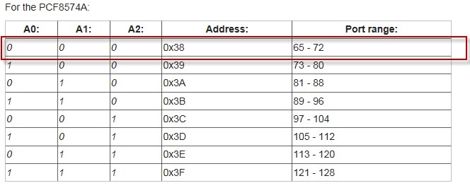
i use PCF8574A by "I2C Scan" the adress return
- if PIN A0-A2 = 0 > 0x38
- if PIN A0-A2 = 1 > 0x3F
The Problem was the adressing in devices
- if use the adress 0x38 you need to use the port range 65-72
- if use the adress 0x3F you need to use the port range 121-128
both adress configuration works
The correct device configuration is: by I2C device on 0x38
with
http://<espip>/control?cmd=pcfgpio,65,1 and http://<espip>/control?cmd=pcfgpio,65,0
it works
thanks for your Supports
Phil
i found the bug it's meeeee
Correct Installation
i use PCF8574A by "I2C Scan" the adress return
- if PIN A0-A2 = 0 > 0x38
- if PIN A0-A2 = 1 > 0x3F
The Problem was the adressing in devices
- if use the adress 0x38 you need to use the port range 65-72
- if use the adress 0x3F you need to use the port range 121-128
both adress configuration works
The correct device configuration is: by I2C device on 0x38
Code: Select all
Device Setting :
Device : Switch input - PCF8578
Name: OUT1
Delay: 0
IDX/Var: 1
Port: 65
Value Name1: Switch
http://<espip>/control?cmd=pcfgpio,65,1 and http://<espip>/control?cmd=pcfgpio,65,0
it works
thanks for your Supports
Phil
Re: PCF8574 - How does it work ?
One question I have , how can I control the ports via MQTT ??
with http it is : http://<espip>/control?cmd=pcfgpio,65,1 and http://<espip>/control?cmd=pcfgpio,65,0
but as with MQTT : ??
with http it is : http://<espip>/control?cmd=pcfgpio,65,1 and http://<espip>/control?cmd=pcfgpio,65,0
but as with MQTT : ??
Re: PCF8574 - How does it work ?
Any news about how to control PCF8574 via MQTT?
Re: PCF8574 - How does it work ?
I am curious about controlling via MQTT as well. Try posting to a new topic with MQTT in the title. That might get the interest of people who are using MQTT.
-
- Normal user
- Posts: 21
- Joined: 31 Oct 2016, 03:03
Re: PCF8574 - How does it work ?
Here a example from my config.json of my homebridge
...
}, {
"accessory": "mqttswitch",
"name": "1",
"url": "mqtt://localhost",
"username": "username",
"password": "password",
"captions": "Power Bar plug 1",
"topics": {
"statusGet":"/PBP/1sw/Sw",
"statusSet":"/PBP/PCFGPIO/65"
},
"onValue": "1",
"offValue": "0",
"integerValue": "true"
}, {
I inversed the onValue and offValue and voilà !!!
Btw, if someone know how to inserted it,let me know ...
Hope that help !!
Re: PCF8574 - How does it work ?
Hello. In the last release of March 2022, did something change in the work of PCF8574? I do exactly as it says here, the LED connected to port 0 does not respond. Everything is connected according to the diagram above. Firmware mega20220328_normal_ESP8266_4M1M
Re: PCF8574 - How does it work ?
What exact command are you using to switch the pin of the PCF ?
/Ton (PayPal.me)
Re: PCF8574 - How does it work ?
he is right...
edit:
just checked all ports...
with mine port 0,2,3,5,6,7 are always high and 1,4 always low
switching them leads only to a short on pulse on the always low pins and an off pulse on the always high pins
i just tested my pcf8574 as an output and it did not work at all....edit:
just checked all ports...
with mine port 0,2,3,5,6,7 are always high and 1,4 always low
switching them leads only to a short on pulse on the always low pins and an off pulse on the always high pins
Last edited by chromo23 on 02 May 2022, 17:30, edited 1 time in total.
Re: PCF8574 - How does it work ?
i gets funky.. changing the address makes it work (the high low issue not the gpio 0 issue)
the discrepancy between the gpio in the command and the actual port still exists
Re: PCF8574 - How does it work ?
I use the command pcfgpio,65,1. Address pcf8574 0x38
chromo23, What address are you using?
Re: PCF8574 - How does it work ?
According to the documentation, the PCFGPIO pins should be addressed from 0 to 255, depending on the I2C address used, where address 0x20 or 0x38 (for the PCF8574A model) starts with pcfgpio 0.
This is apparently changed in the software since this (quite old) thread was started and last updated.
/Ton (PayPal.me)
Re: PCF8574 - How does it work ?
pcfgpio,0,1 ...is bulls**t ...sorry (it starts with pcfgpio,1,1)
i was confused because while i was testing under the standard address 0x20 and got weird feedback from the leds
You use the pcf8574a which uses other adresses.
i was confused because while i was testing under the standard address 0x20 and got weird feedback from the leds
I use 0x20 which doesn’t work and only tried 0x21 which is working.
You use the pcf8574a which uses other adresses.
Re: PCF8574 - How does it work ?
Yes, i just found outAth wrote: ↑02 May 2022, 17:08 According to the documentation, the PCFGPIO pins should be addressed from 0 to 255, depending on the I2C address used, where address 0x20 or 0x38 (for the PCF8574A model) starts with pcfgpio 0.
This is apparently changed in the software since this (quite old) thread was started and last updated.
Re: PCF8574 - How does it work ?
have you tried another port and/or another address?
Re: PCF8574 - How does it work ?
for me only another address seems to work. i would start with that...
Re: PCF8574 - How does it work ?
Does not work. I do not understand why. Went through all available pcf8574 addresses...
Re: PCF8574 - How does it work ?
and you changed the command according to the address?
Unfortunately i have only the pcf8574 without an a to test. Maybe the bug concerns only the base address 0x20 but maybe not.....
What is the output when you enter the command? A picture of the circuit could be also helpful.
Re: PCF8574 - How does it work ?
I testet the pcf8574 again after a factory reset. and it seems to work fine in output mode regardless which address is used (don´t know what happend yesterday)
@sartam:
what you can try for testing is to use the latest release on your device do a factory reset and only connect the pcf8574 and the led as in the picture at the beginning of the post. You don´t need R1 and R3 if you have a board like this: Do an ic2scan to see if it is present..
Then activate rules and enter the code below to change all pins to output mode:
Reboot! (you could enter this command into the commandfield unter /tools as well, but i had somehow issues with this)
Then enter the command under /Tools in the commandfield:(or change it to whatever pin you have the led connected to)
@sartam:
what you can try for testing is to use the latest release on your device do a factory reset and only connect the pcf8574 and the led as in the picture at the beginning of the post. You don´t need R1 and R3 if you have a board like this: Do an ic2scan to see if it is present..
Then activate rules and enter the code below to change all pins to output mode:
Code: Select all
on system#boot do
PCFmodeRange,65,72,0 // this is the range for the default address 0x38 of the pca8574
endon
Then enter the command under /Tools in the commandfield:
Code: Select all
pcfgpio,65,0
Re: PCF8574 - How does it work ?
An interesting thing. I'll try, of course. I'm not using a module, but just a microcircuit in a dip package. But this should not be an obstacle. I will definitely try.
Re: PCF8574 - How does it work ?
It is working! The only remark. I connected the microcircuit to 5 volts. Although the datasheet says that the power is in the range of 2.8-5.2 volts
Re: PCF8574 - How does it work ?
Great you have it working now!
Working with the chip at 5V may cause issues on the I2C bus, as that is 3.3V for ESP's, but the Wemos and NodeMCU units seem to be able to handle 5V signals without damage.
So if you can use it at 3.3V that is the advised route.
Working with the chip at 5V may cause issues on the I2C bus, as that is 3.3V for ESP's, but the Wemos and NodeMCU units seem to be able to handle 5V signals without damage.
So if you can use it at 3.3V that is the advised route.
/Ton (PayPal.me)
Re: PCF8574 - How does it work ?
Yes, of course I know about this feature. But, as they say, you can't argue with facts. Also, an LSD 2004 display is connected to 5 volts, and it works fine.
Re: PCF8574 - How does it work ?
The main thing to keep in mind is that when connecting several sensors/chips to the same I2C bus, you must make sure they all can handle the 5V on the SDA/SCL lines.
Re: PCF8574 - How does it work ?
Often, information about the capabilities of the operation of slave devices on the I2C bus from 5 volts with a general power supply of the circuit from 3.3 volts often flashes before my eyes.
Who is online
Users browsing this forum: No registered users and 2 guests