Connecting a Rain Gauge
Moderators: grovkillen, Stuntteam, TD-er
Connecting a Rain Gauge
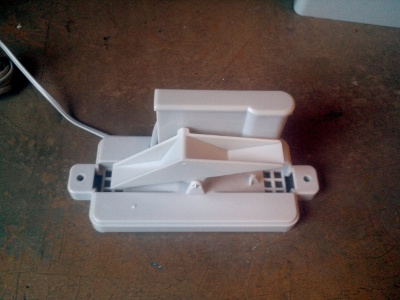
So I bought one of those really cheap rain gauges with a tipping bucket that looks like image just below, connected one wire to ground and the other to D5 on my nodemcu board but would love to get some help on the config since I can't get it working and an inch from going completely mad here...
This is the model:
This is how I have set it up, not sure what I should select in the Counter Type and Mode Type?
The result is that the Count stays at 0 and the Total just increases for each tipping but ignores the formula?
This is the model:
This is how I have set it up, not sure what I should select in the Counter Type and Mode Type?
The result is that the Count stays at 0 and the Total just increases for each tipping but ignores the formula?
Re: Connecting a Rain Gauge
All in all looks like it's working ok., just the formula is not working. Why I don't know.
You could work around with rules and a dummy. That would allow a local representation of rain for last h, last 24h, so on. The count value represents the count between delays. Increase delay for that purpose.
Domoticz on Raspi 2 -- 14 ESP units (hacked Sonoff,NodeMCUs, Wemos, self-built units) running with RC140- Mega 2.0.0 dev8
Re: Connecting a Rain Gauge
Thanks, and yes, seems to kind of work when I subbed to my mqtt
I'll try and up the delay to 60s so that it doesn't spam my server every second tough. Still, would be great to know what the different "Counter Types" does!
- budman1758
- Normal user
- Posts: 301
- Joined: 15 Apr 2017, 05:13
- Location: Riverside CA USA
Re: Connecting a Rain Gauge
I set up a pulse counter a while ago for fan RPM. The formula you want is the count divided by the delay time times the amount of rain is in 1 bucket.
I would set your delay time to 5 minutes or so. Assuming your rain gauge is .2794 inches per bucket (which seems like a lot to me) Then the formula would be something like this:
That gives you the amount of rain in the last 5 minutes. You can adjust that to any time delay you need but your reading is always going to be so much rain in such amount of time. The total will keep counting up until the next reboot. The time value I could never make sense of in my setup. It was always somewhere between 1 and 4 for me with a 60 second delay.
Keep in mind that your values will be lost whenever the ESP reboots. If you are looking to track rain for any length of time you might want to consider a save mechanism of some sort.
I would set your delay time to 5 minutes or so. Assuming your rain gauge is .2794 inches per bucket (which seems like a lot to me) Then the formula would be something like this:
Code: Select all
%value%/300*.2794 << using the "Count" value
Keep in mind that your values will be lost whenever the ESP reboots. If you are looking to track rain for any length of time you might want to consider a save mechanism of some sort.
"The glass is twice as big as it needs to be".
Re: Connecting a Rain Gauge
Thanks @budman1758 I'll go with that formula instead!
It's not inches but mm btw, so it would compare to 0.011"
Using node-red to parse the data and send it off to influxdb for storing and then Grafana to show it! This is how it looked last night when playing around with it!
https://snapshot.raintank.io/dashboard/ ... lRJyDpeTl6
It's not inches but mm btw, so it would compare to 0.011"
Using node-red to parse the data and send it off to influxdb for storing and then Grafana to show it! This is how it looked last night when playing around with it!
https://snapshot.raintank.io/dashboard/ ... lRJyDpeTl6
- budman1758
- Normal user
- Posts: 301
- Joined: 15 Apr 2017, 05:13
- Location: Riverside CA USA
Re: Connecting a Rain Gauge
That makes a bit more sense.
"The glass is twice as big as it needs to be".
-
- Normal user
- Posts: 29
- Joined: 02 Dec 2020, 15:30
Re: Connecting a Rain Gauge
I'm very sorry for digging out that old thread, but I could not find an answer somewhere else.
I have bought a rain gauge that looks similar to the one in the first posting.
It seems to work at a first glance, but after monitoring it for a while I see that the pulse counter rises now and then although the bucket is not moved.
I have connected one wire to GPIO34 of an ESP32, the second wire to ground. In addition GPIO34 has a pullup to 3V3.
The problem disappears if I disconnect the rain gauge.
Somewhere else I was advised to introduce some additional hw-logic (transistor and some resistors) to avoid interference.
Does anybody else face a similar problem and maybe has an easier solution?
Furthermore I see that the pulse counter does not work if I set the trigger to "LOW" although the GPIO is definitly LOW when the reed-contact closes. It is working properly for "RISING" and "FALLING". Any idea on that?
Re: Connecting a Rain Gauge
Judging the GPIO pins you use, you seem to be using an ESP32.
The support for pulse counter on ESP32 is still on my todo list as the CPU itself does have hardware support for it which we don't use yet.
This will make it much more reliable.
It sounds like you're picking up noise. Maybe a long cable?
The support for pulse counter on ESP32 is still on my todo list as the CPU itself does have hardware support for it which we don't use yet.
This will make it much more reliable.
It sounds like you're picking up noise. Maybe a long cable?
-
- Normal user
- Posts: 29
- Joined: 02 Dec 2020, 15:30
Re: Connecting a Rain Gauge
Yes, as written above. In detail it's a DevKitC (or at least it's labelled as a DevKitC).
Sounds great.
I want to have my automatic watering control running in spring, as of now I plan to use the soil moisture sensors for evaluating the demand of water, the rain gauge is just an add-on to see if the moisture is plausible.
Unfortunately it does not sound like the pulse counter with HW-support will be ready by then?
Currently the cable is approx. 3m, I have already tried placing the rain gauge somewhere else where the whole length of the cable is needed, but it does not make a difference. At the end it has to be approx. 7m long, as the gauge will be placed on top of the garage and then be approx. 7m away from the control unit.
I've also tried different pull-ups and also switching to HIGH instead of LOW, but the problem is still there. I see that the counts often happen together with switching on some lights in the house, one time early in the morning I could reproduce it by switching-on my IT-equipment, but when I tried it again I could not see the counter rising again.
Re: Connecting a Rain Gauge
The last few months have been more about actually fixing stuff and improving, instead of bug hunting as we have had no idea for quite a long time what was causing issues.
So it is not that unlikely supporting the specific ESP32 features will be done in the next few months.
For example in the last 2 weeks I've been working on improving/adding specific PWM related features of the ESP32, which are done in software on the ESP82xx.
But I doubt adding support for the hardware specific pulse count features of the ESP32 will fix your issues.
What I think is happening here is that your GPIO pin picks up some peak signals from noise or switching of appliances you mentioned.
This means the signal level actually does change and what the HW pulse count options of the ESP32 may fix is not missing a pulse.
What you need to do is one or more of these:
- increase the "debounce time"
- For longer cable: twist the wires so a signal received will be cancelled out by the next twist in the cable.
- Make it harder to switch state (more on that below)
About making it harder to switch state.
You can try to keep the signal high when not counting a pulse, so it will be connected to GND when a pulse must be counted.
For example by using a relatively strong pull-up and let the switch draw it to GND.
Still there is no current flowing when the switch in the sensor is not closed, so you may also want to place a resistor with a relative high value over the sensor itself (at the sensor location) to draw a small current through the long wires.
For example a pull-up resistor of 2k2 and a resistor of 10x that value over the sensor. (just some value, doesn't matter a lot, as long as the ratio between both values is large enough)
Then any noise picked up must have quite some energy to change the state of the signal as there is already some current flowing.
-
- Normal user
- Posts: 29
- Joined: 02 Dec 2020, 15:30
Re: Connecting a Rain Gauge
That's what I've already tried, I've had pullups down to 3k already.
I could give that a try, but have to get some additional resistors next week, currently I have not bigger than 10k here and don't want to go down below 3k for the pullup.TD-er wrote: ↑10 Dec 2020, 13:45 Still there is no current flowing when the switch in the sensor is not closed, so you may also want to place a resistor with a relative high value over the sensor itself (at the sensor location) to draw a small current through the long wires.
For example a pull-up resistor of 2k2 and a resistor of 10x that value over the sensor. (just some value, doesn't matter a lot, as long as the ratio between both values is large enough)
Then any noise picked up must have quite some energy to change the state of the signal as there is already some current flowing.
Re: Connecting a Rain Gauge
You can also add some 10k's in series
-
- Normal user
- Posts: 29
- Joined: 02 Dec 2020, 15:30
- Andrew Mamohin
- Normal user
- Posts: 102
- Joined: 12 Jun 2020, 08:30
- Location: Belarus, Gomel
- Contact:
Re: Connecting a Rain Gauge
This is an old thread, but maybe it will be useful for someone. I bought myself a reed switch rain gauge and experimented with it for a while.
I achieved good performance without false pulses when I put a non-polar 0.01 microfarad capacitor between the microprocessor pin and the power supply minus.
This is how the scheme turned out:
I achieved good performance without false pulses when I put a non-polar 0.01 microfarad capacitor between the microprocessor pin and the power supply minus.
This is how the scheme turned out:
Andy.
Re: Connecting a Rain Gauge
This can also be used for any other switch with relatively long wires.
Who is online
Users browsing this forum: Bing [Bot] and 2 guests